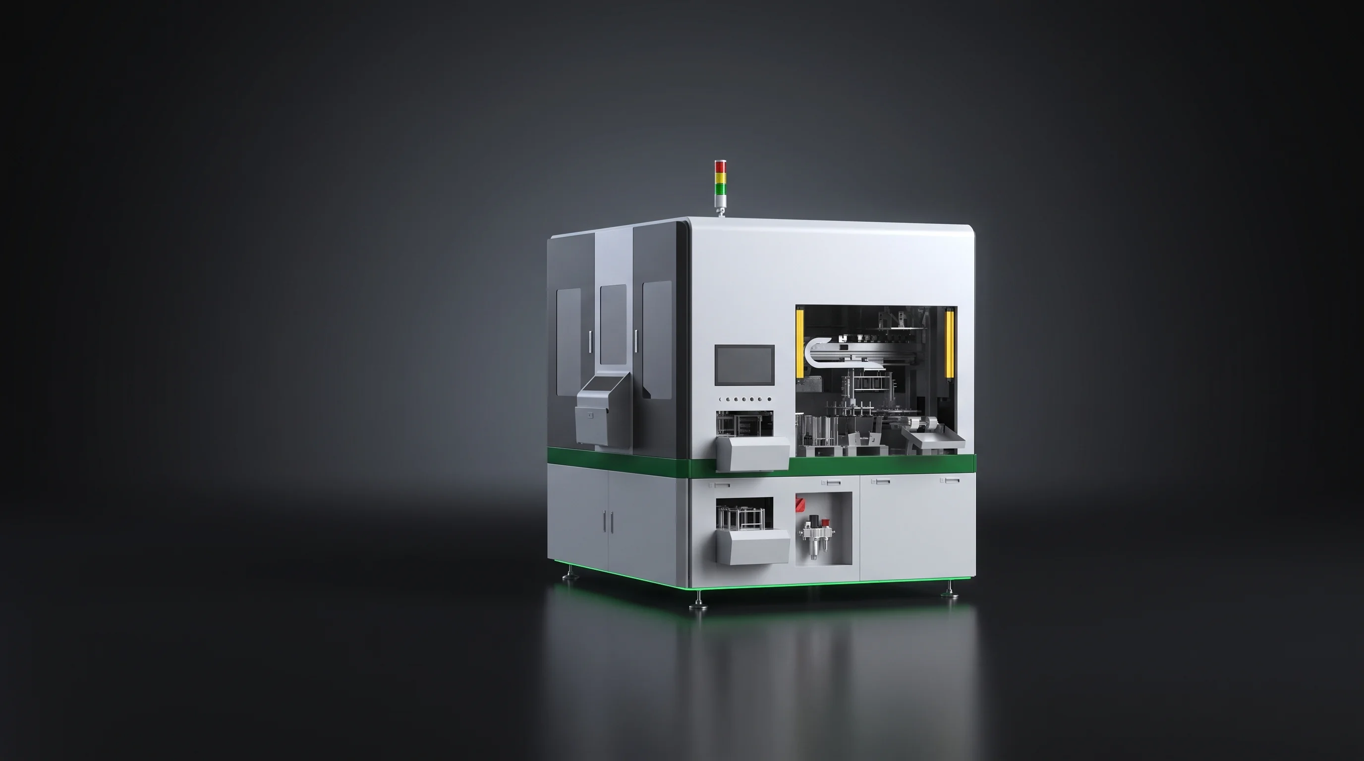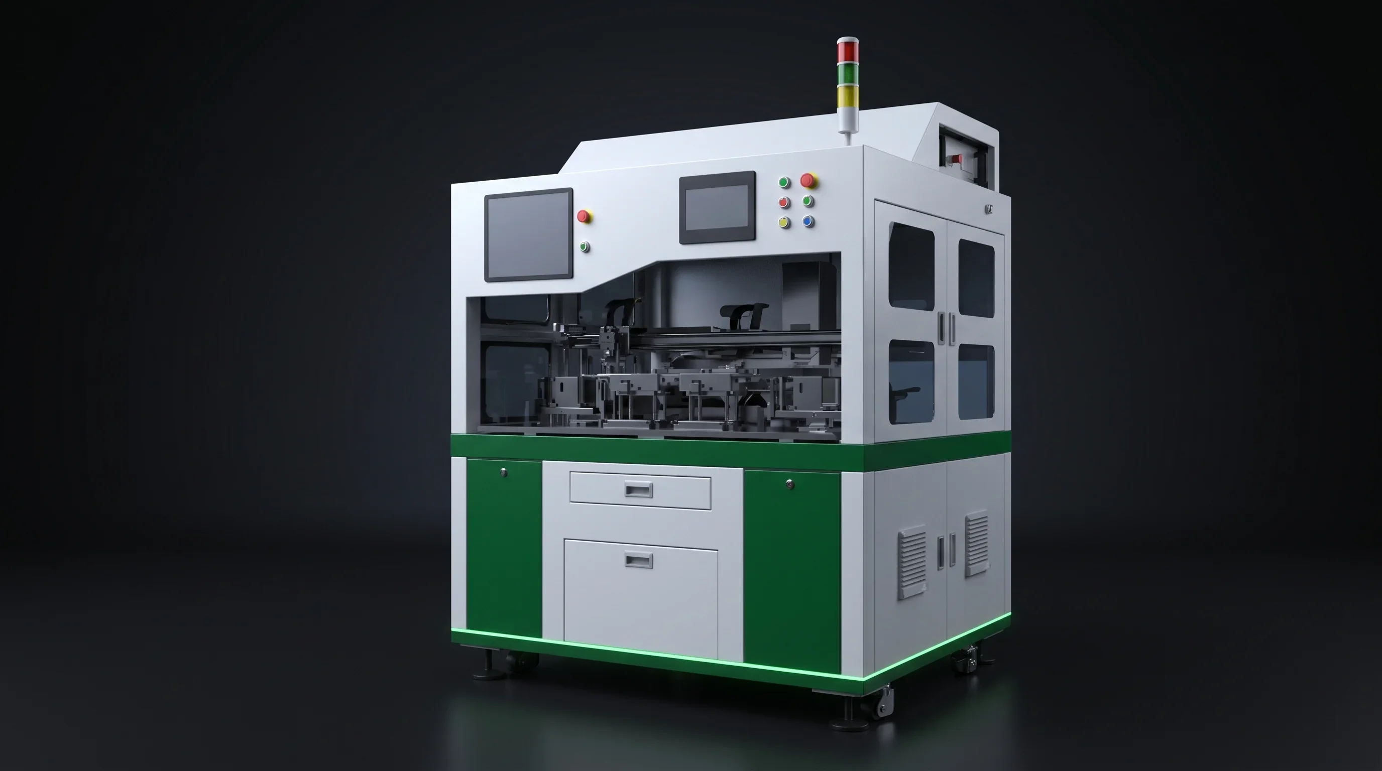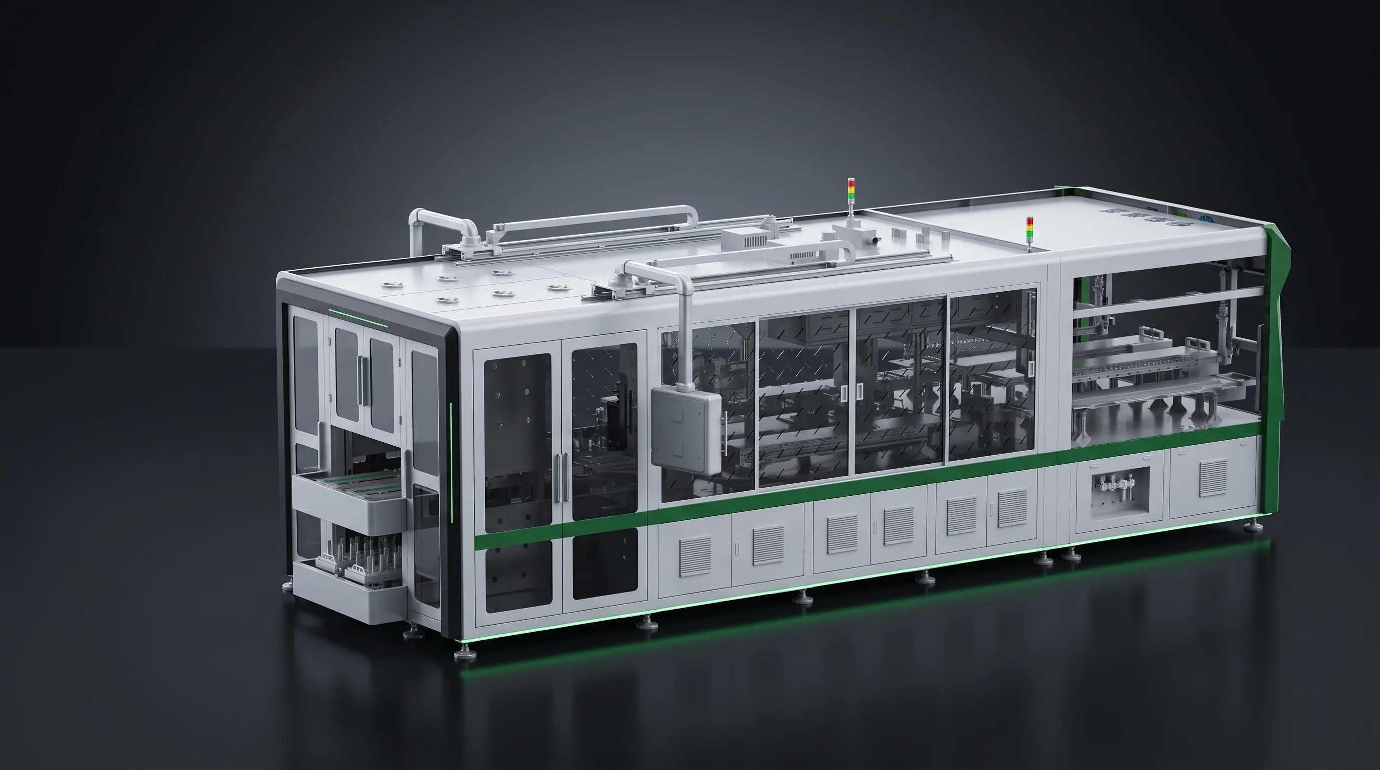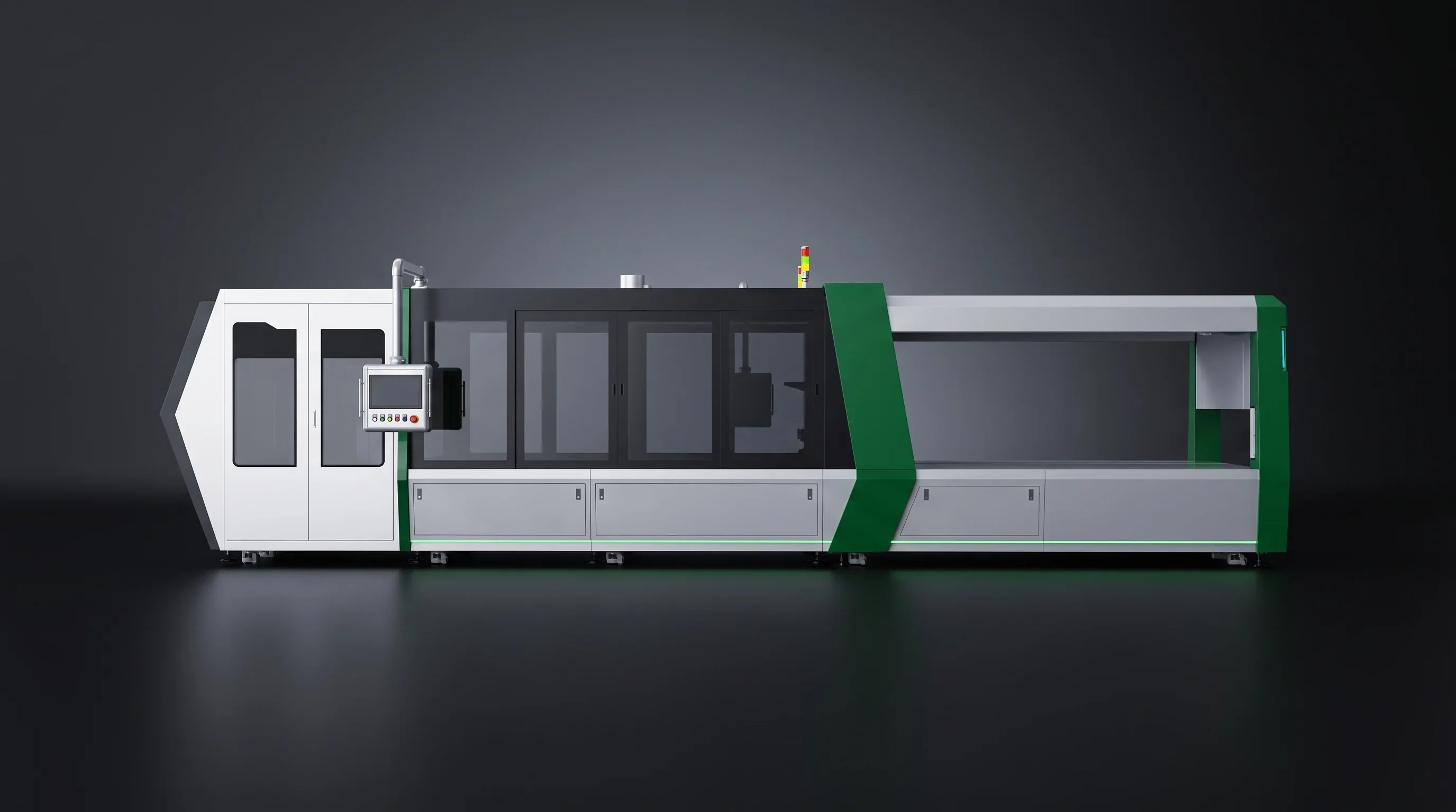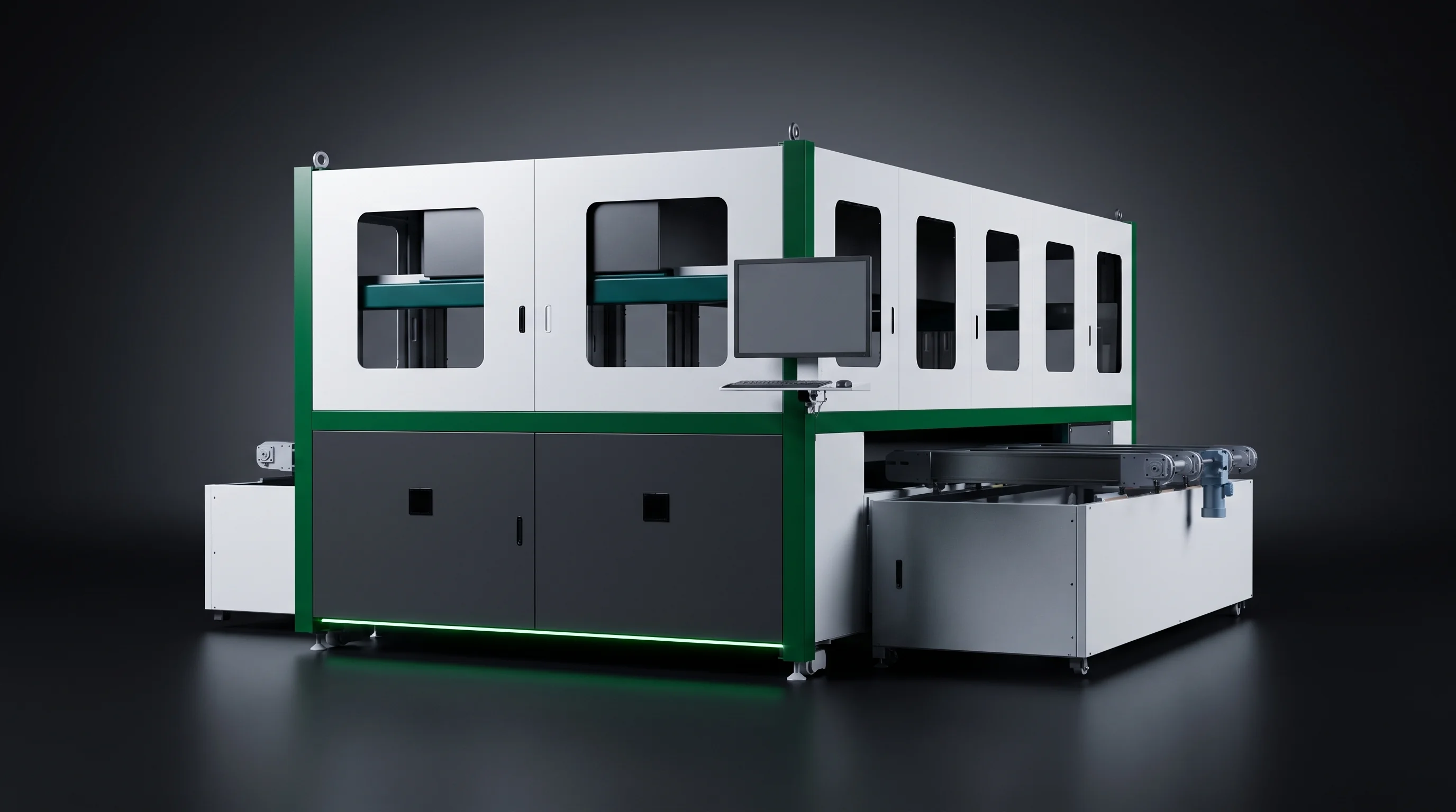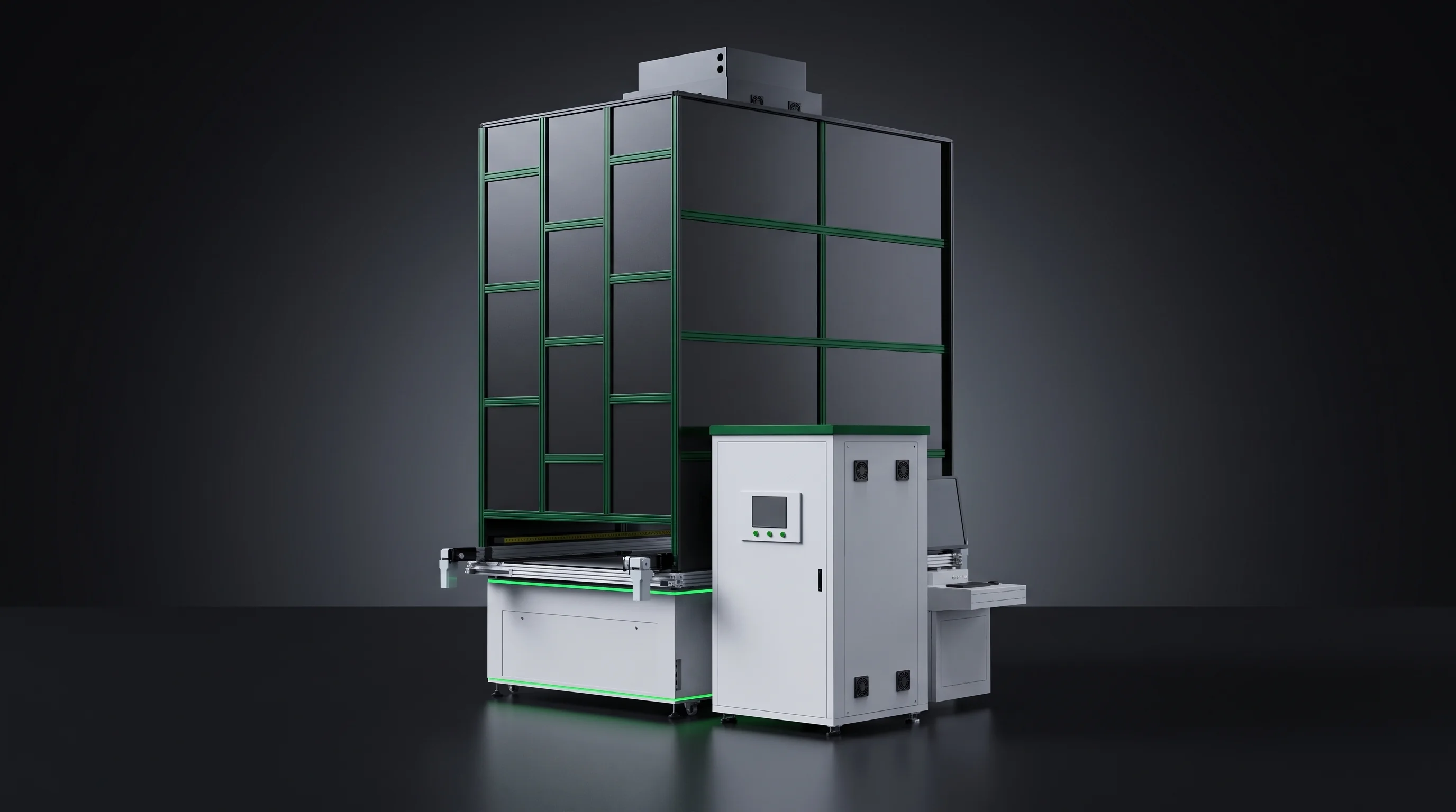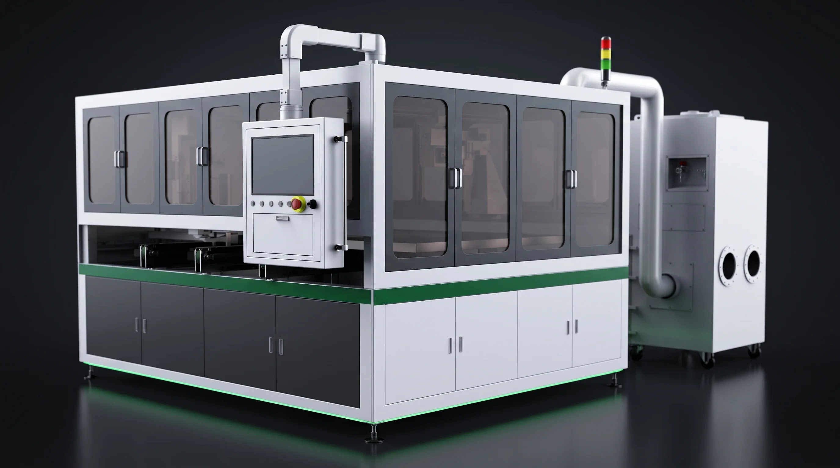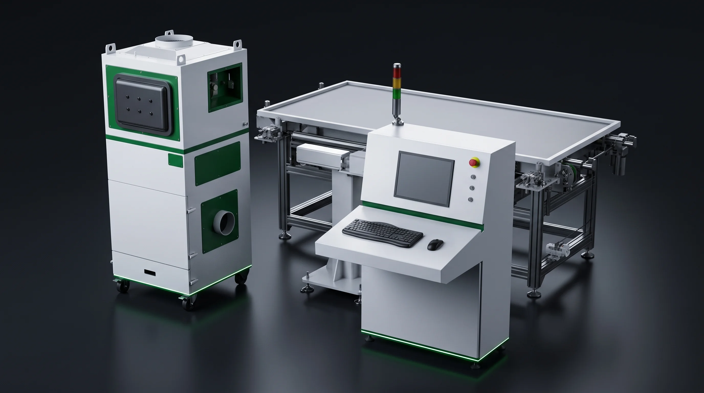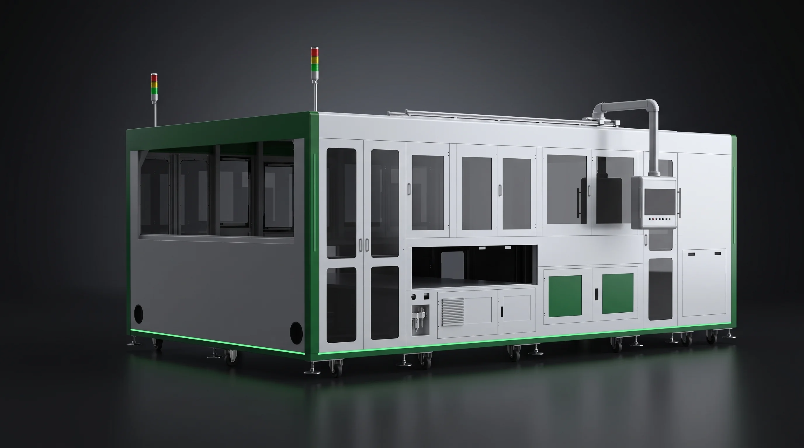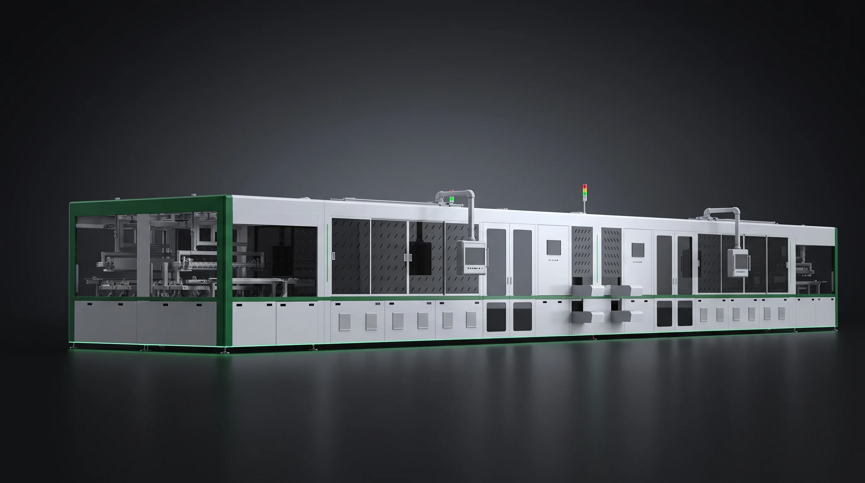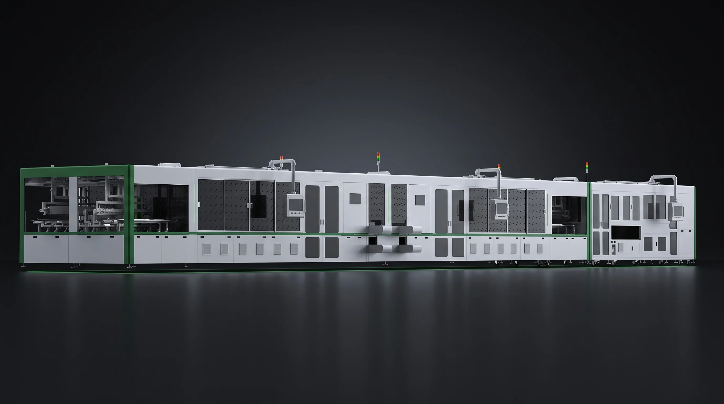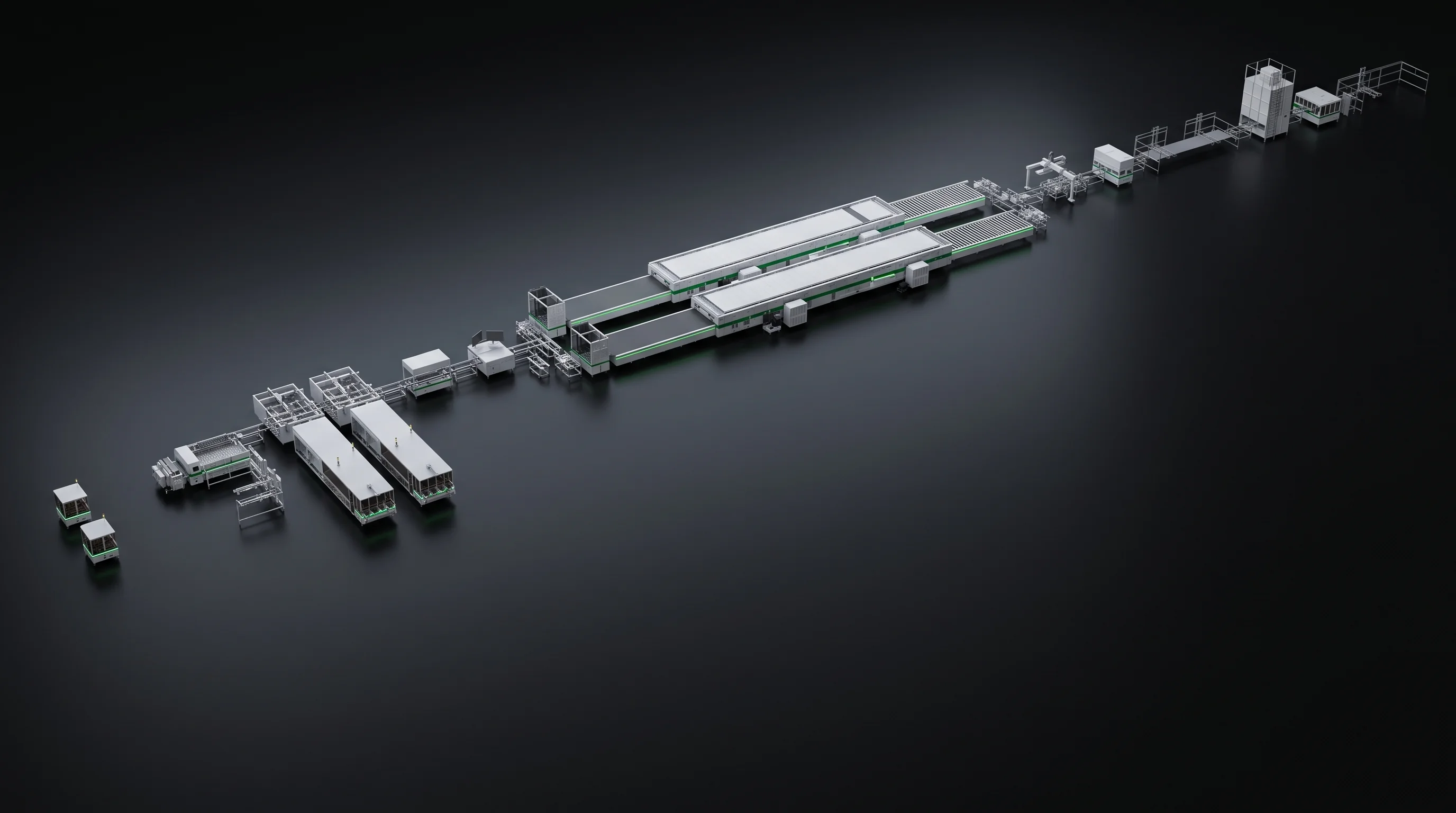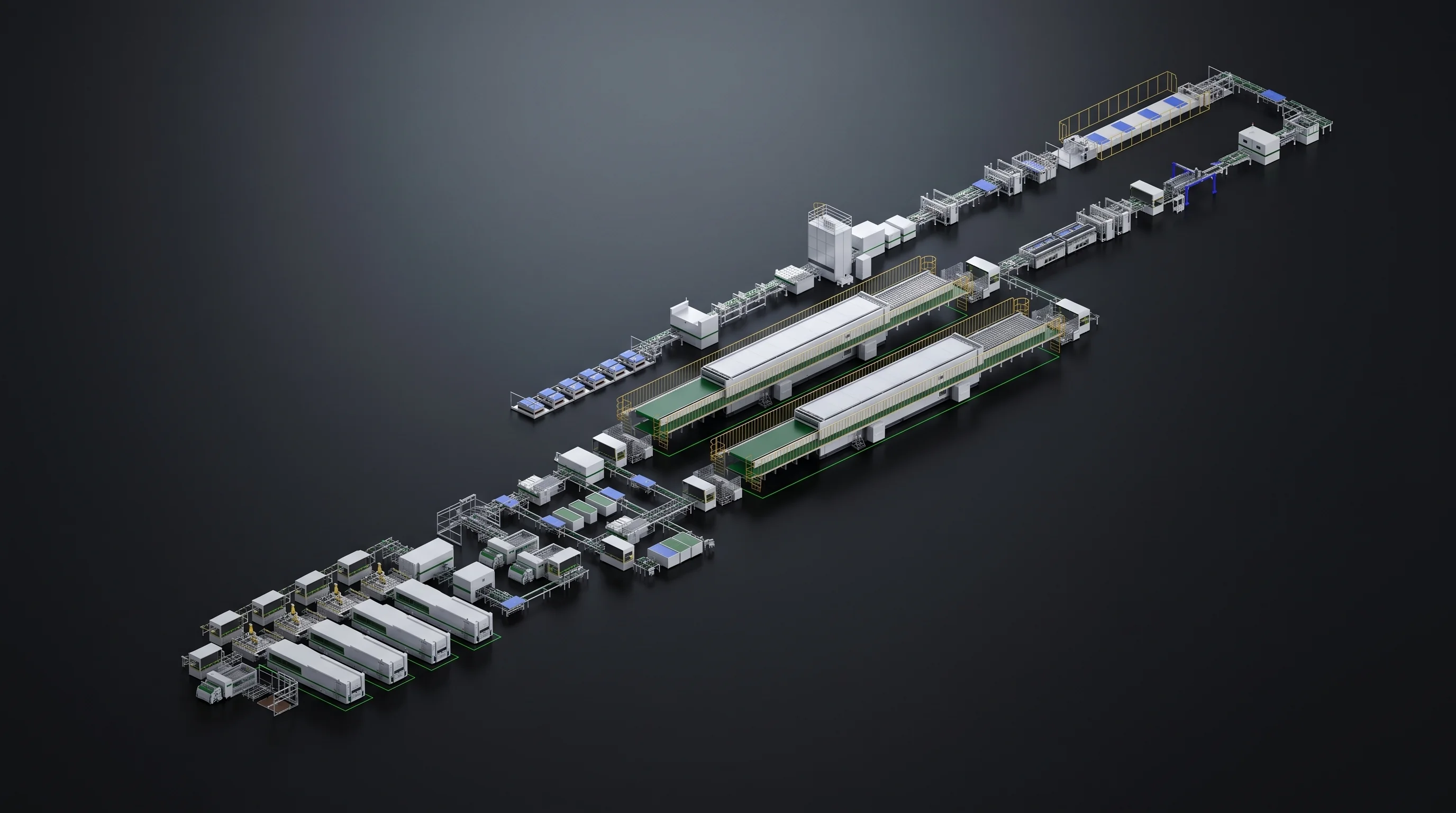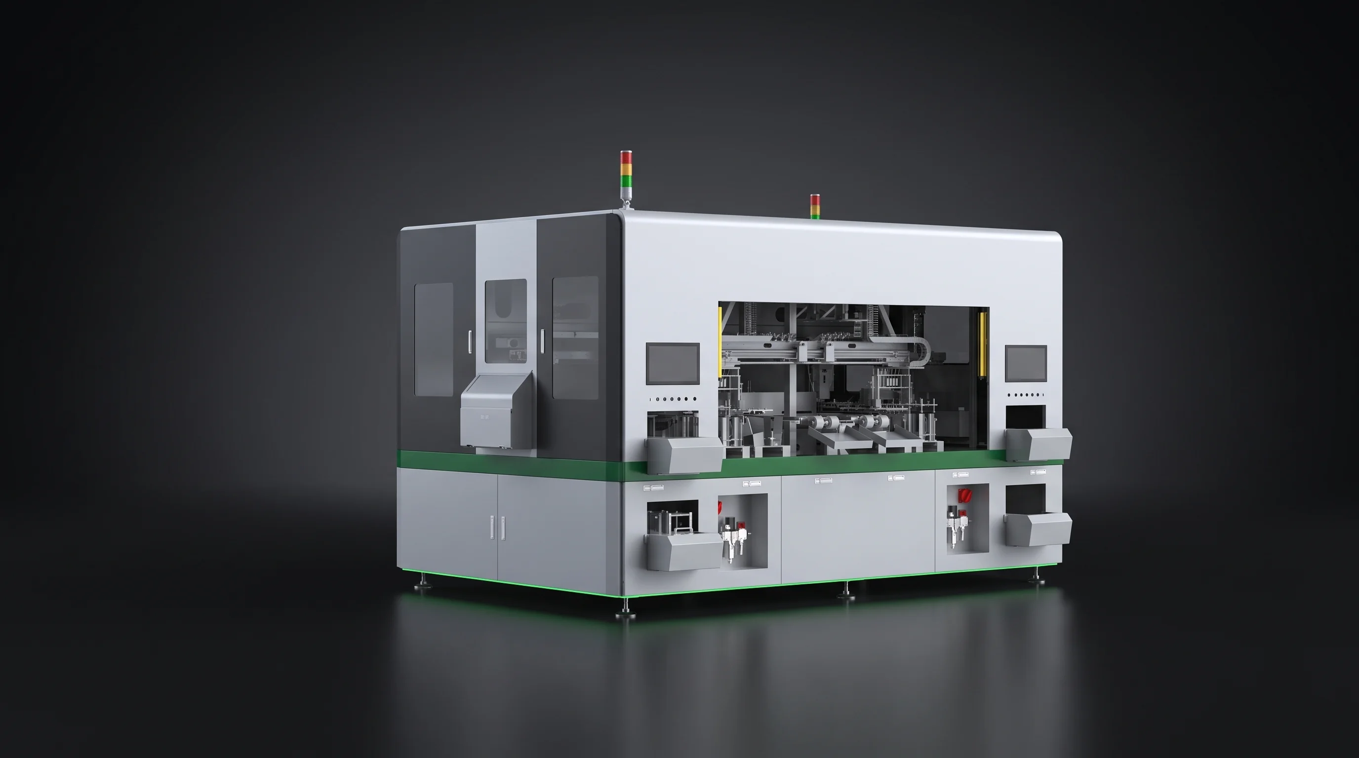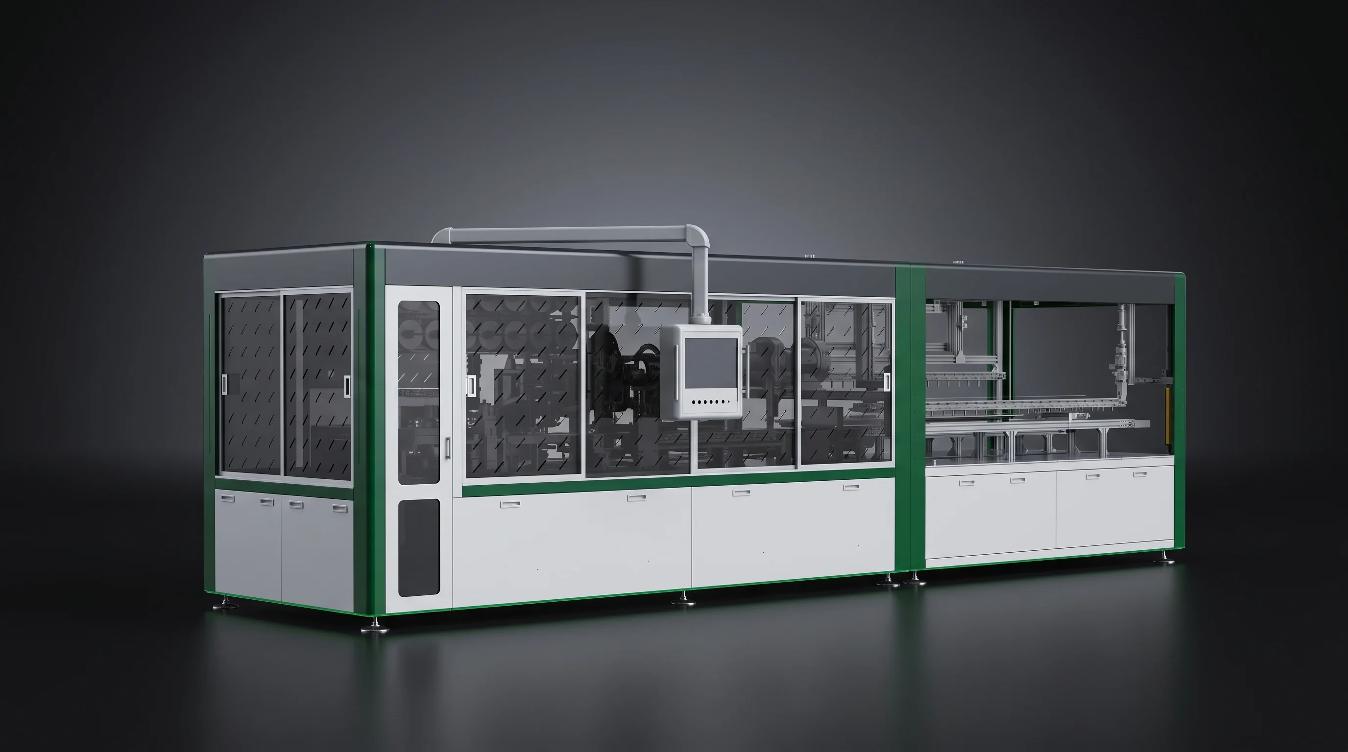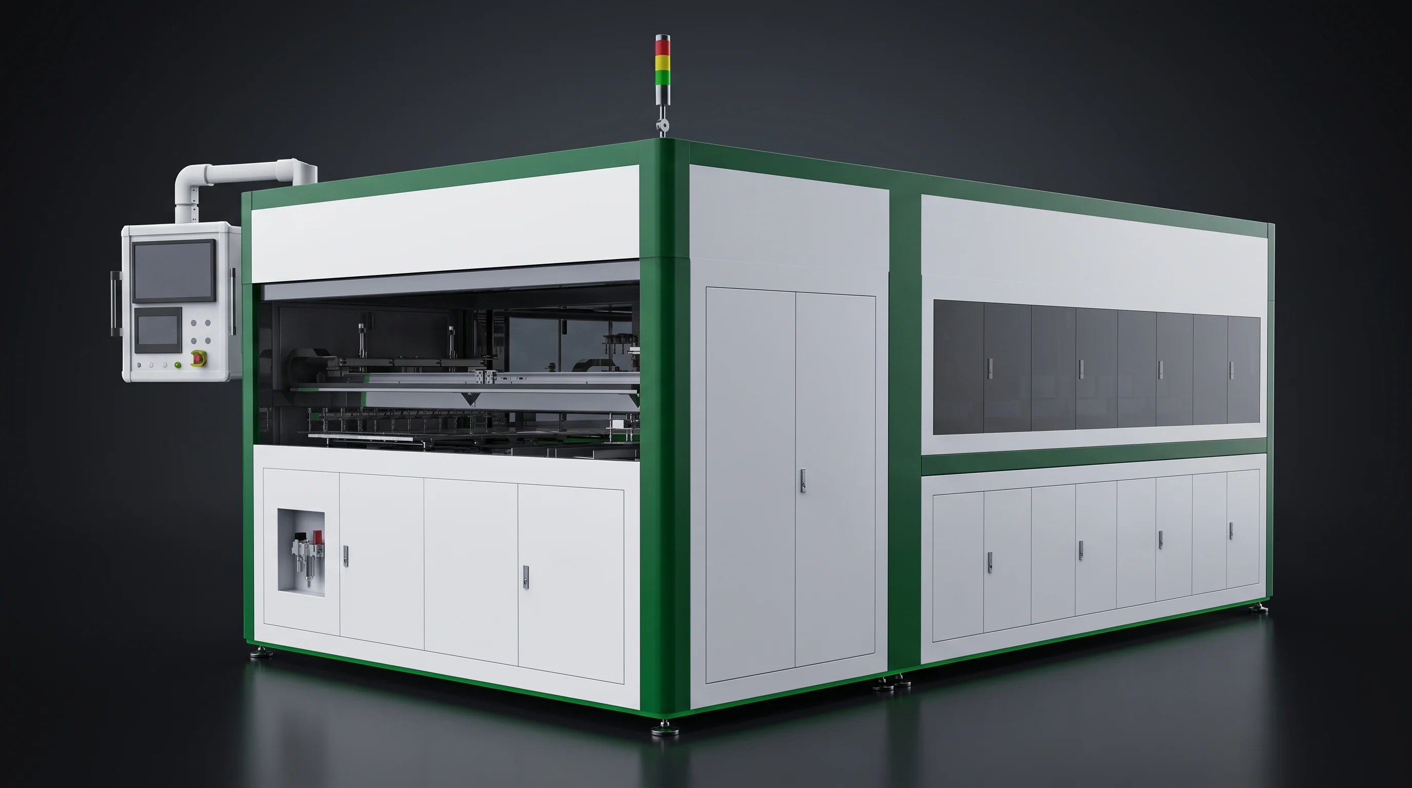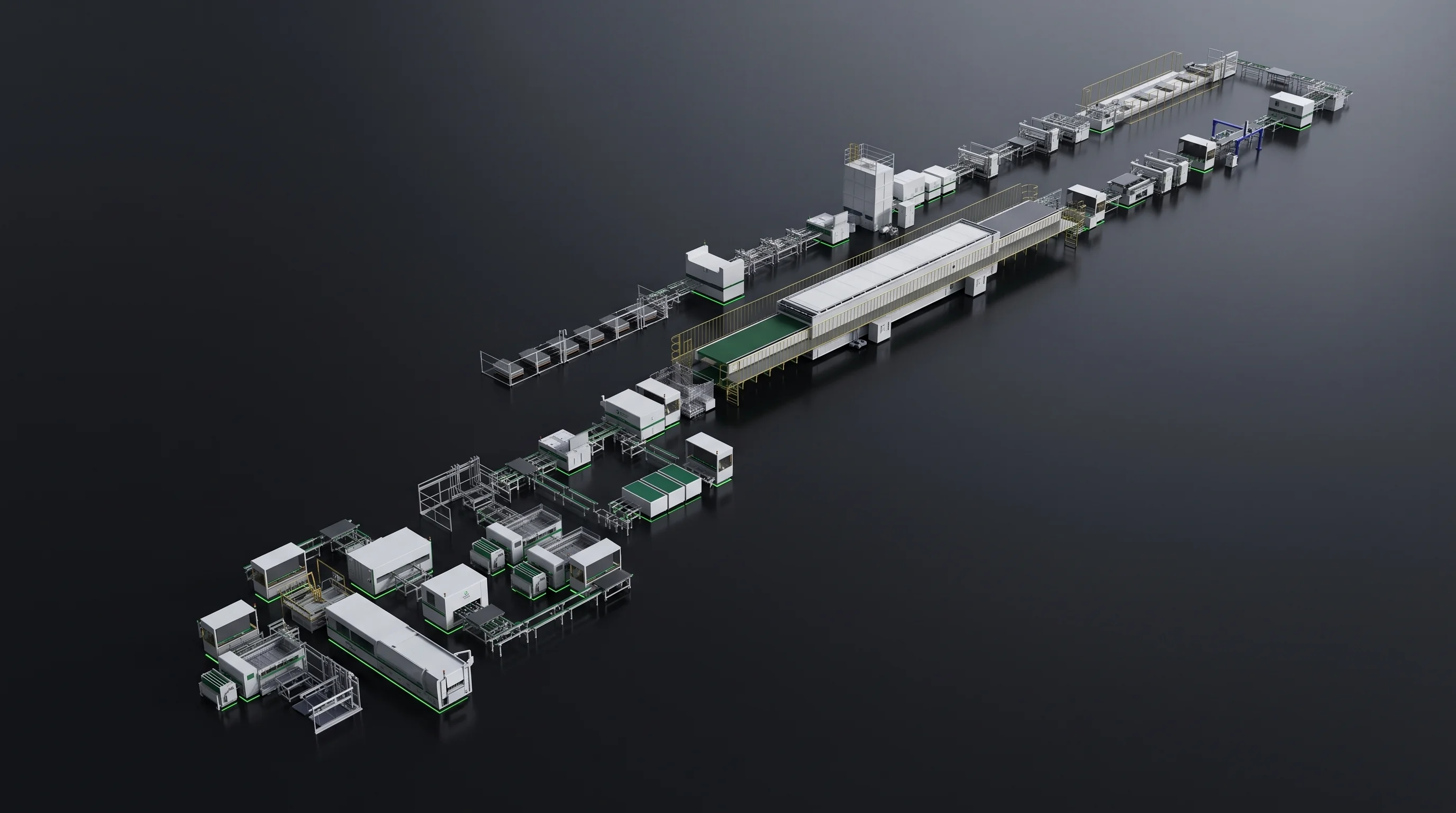
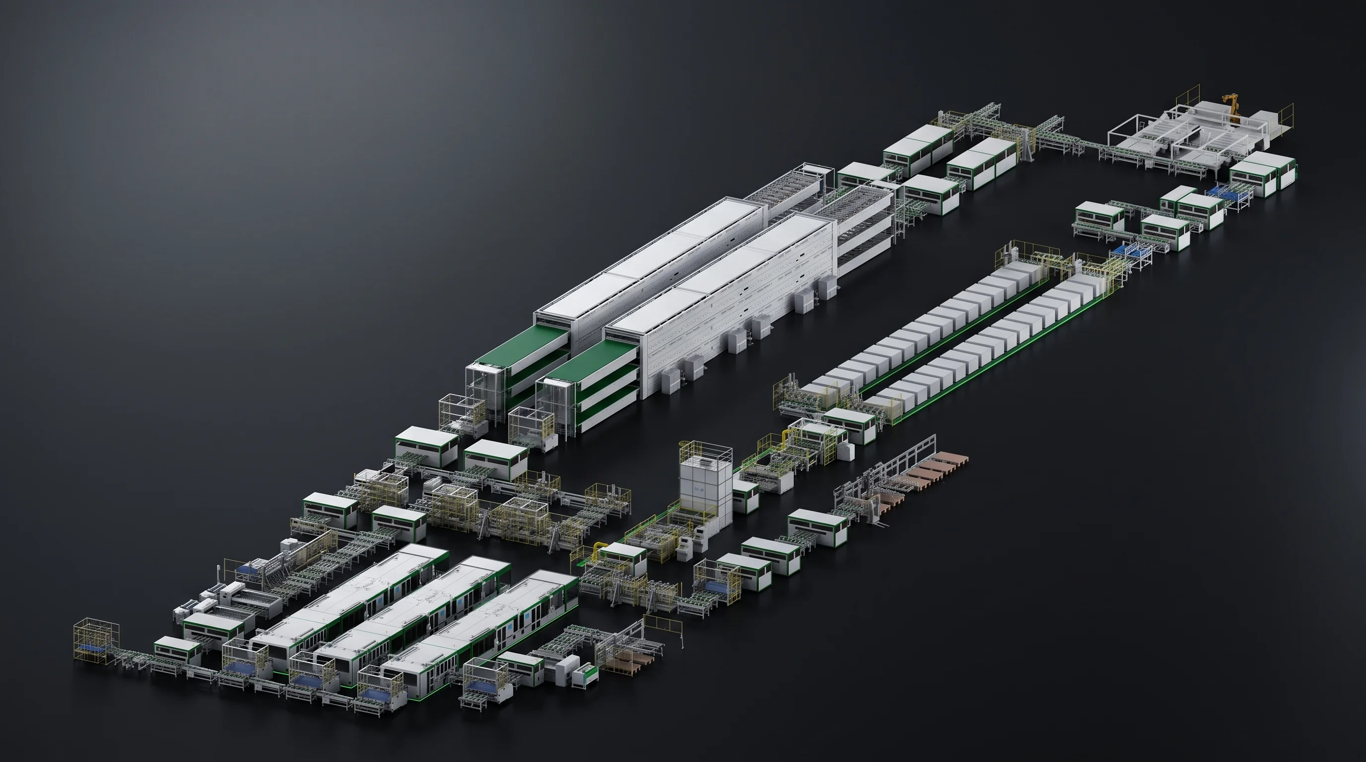
L-shaped solar panel production line under studio light, two straight runs joined at the layup station

Cell in, marked frame out

Solar Panel Production Line, Cell to Frame Marking

A solar panel production line from SolarModule Line starts where the tested cell arrives on your floor and ends where the finished module carries its own identification. Six stations sit in that span: scribing, stringing, layup, bussing, test and marking. Three things decide the rest — the string your stringer produces, the height two machines hand over at, and whether process steps sit in separate frames or in one.

  • ● New floor
  • ● BC upgrade to a TOPCon or PERC row
  • ● One replacement station

Two flows, one junction

Strings arrive from the row behind. Glass arrives on its own conveyor beside it. Everything downstream of the layup station is set by where they meet.

Strings from the stringer 1230 mm docking Glass on its own conveyor 950 ±50 mm LAYUP Long edge first 1–10 mm spacing
The junction sets the direction of the whole row

Settle these first

Four Numbers Fix a Solar Panel Production Line

A machine can meet its own parameter table in full and still fail to join the row, if the quantities that live between two machines were never written down by either of them.

Agreed with your engineer before any layout drawing is issued, then marked on it.

String length 540 – 1400 mm Sets module length and reaches into the layup window. Settle it late and the layup station gets re-specified after it was chosen.
Stringer to layup 1230 mm The docking height where the two main frames meet. Designed in on the drawing, not shimmed under machine feet on site.
Glass in and out 950 ±50 mm A separate height for a separate flow, matched to the glass conveyor coming from your washing and loading equipment.
String spacing 1 – 10 mm With cell pitch, it decides how the string fills the module — held without correcting each string, because straightness is ±0.5 mm.
All four then go into the parameter tables of the technical agreements. Acceptance is judged against those tables, so an interface number that never reached a table is an interface nobody has to meet.

Station order

Solar Panel Production Line Station Order

The order we work from is the BC crystalline-silicon module line blueprint, and it runs as one main flow with one side flow joining it. Read as a row on the floor, our span is two straight runs joined at the layup station, with your lamination and framing equipment between them. The first three stations sit in one line with no cross traffic; the last two pick the panel back up after it returns from your side of the floor.

MAIN FLOW → 01SCRIBING 02STRINGING 1230 mm 03LAYUP GLASS CONVEYOR · 950 ±50 mm · SHORT EDGE IN 90° turn long edge first 04BUSSING YOUR LAMINATOR 05EL + IV 06MARKING ← RETURN RUN SIX STATIONS IN OUR SPAN
Two straight runs joined at the layup station. The dashed frame is yours, not ours.

Swipe the diagram

Station 01

Scribing, at the magazine end

Full cells go in at the magazine end and cut cells travel forward into the stringer, which is set in line behind it.

In
Full cells from the magazine, inspected at loading
Out
Half or one-third cells, inspected again at unloading, rejects already off the line
Rejects stop here

Station 02

Stringing, in the same straight row

Strings leave at the output end and are picked directly by the layup robot.

In
Cut cells in the loading format the scribing station committed to
Out
Strings — scriber, stringer and layup form one straight row on the floor, with no cross traffic between them and no buffer to design
One straight row

Station 03 · the junction

Layup, where the two flows meet

Glass reaches this station on its own conveyor at its own height, entering on the short edge and leaving on the long edge.

In
Strings at 1230 mm from the row behind, glass at 950 ±50 mm from the conveyor beside it
Out
A laid-up panel travelling long edge first, which sets the direction of every station downstream of it
Travel direction turns 90°

Station 04

Bussing, then out of our span

String ends are joined into the module circuit and the panel leaves with its complete electrical layout in place.

In
The laid-up panel from the junction
Out
A bussed panel, handed to your laminator at the interface you specify
Handover to your laminator

Station 05

EL and IV test, after lamination

Testing rejoins the flow once the panel comes back from lamination.

In
The laminated module from your side of the floor
Out
A measurement record as much as a panel — its position at the end of the flow is what makes the rest auditable
Record your quality team files

Station 06

Frame marking, at the exit

The last station in our span puts identification onto the finished module, after framing.

In
The framed module off your framing line
Out
A module in the field that can be traced back to its batch
Closes the batch record
Complete solar panel production line seen in isometric view, scriber through to marker in one row
The same span seen as equipment: six stations, two runs, one handover to your lamination and framing line.

Station 01 in detail

Scribing Station Feeding the Stringer

What this station commits the line to is the piece the stringer will load. Cut length, piece count per magazine and cell thickness all have to match the stringer's loading format.

SML-C72: laser grooving and thermal cleaving, water cooling at the cut, heated drying downstream. Breakage 0.05% or less on A-grade cells.

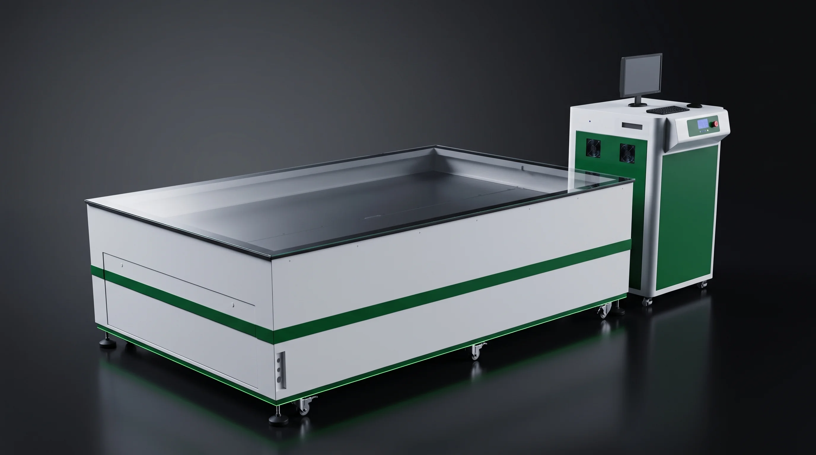
Laser scribing station on a solar panel production line, magazine loading end facing the stringer row
Full cells in at the magazine end, cut cells forward into the stringer set in line behind it.
Two source classes, one station slot. The SML-C72 runs 4800 BC full cells an hour, 6800 on TOPCon or PERC in dual line. The SML-C20 uses a 30 W Q-switched source at 1064 nm, 40 micron kerf, automatic cleaving and placing, 1600 full cells an hour or better. Its standard tooling covers 166 to 182 mm two-part splits; anything else is tooled to order.

Checked at loading

  • Position
  • Edge chipping
  • Missing corners
  • Cracks
  • 90° flip
  • Contamination
  • Scratches

Rejects are taken out here, before the stringer sees them.

Checked at unloading

  • Clean split
  • Piece size

Both results matter downstream. Ask for the two inspection lists by name.

Laser scriber gantry and cleaving section, cells 120 to 220 microns thick

The number that reaches forward

String Length Sets the Whole Row

Module length, string spacing and the glass handling all follow from the string. Settle it late and a change there reaches forward into equipment that has already been quoted.

Straightness on the SML-S60 is held to ±0.5 mm — that is what lets the layup robot place a string against its neighbour without correcting each one.

STRING LENGTH · SML-S60 540 mm 700 900 1100 1400 mm SML-S40 MAXIMUM
At a fixed string length, cell pitch decides how many cells the string carries.

Swipe the diagram

BC tabber stringer output end, where the string leaves at the length written into the agreement
String-forming figures on the three stringers
What is fixedSML-S60SML-S40SML-S15
String length540 to 1400 mm1400 mm maximumFollows the module drawing
Cell pitch−1 to −0.5 mm, and 1 to 5 mm1 to 5 mm, positive only1 to 5 mm, positive only
Cell size166 to 210 mm BC166 to 210 mm half cells166 to 210 mm
Busbars3BB to 20BB, 25BB by tooling3BB to 20BB, 25BB by tooling3BB to 20BB

Swipe the table

Layup window, length 1650–2500 mm String length plus busbar overhang plus edge margin falls inside this side.
Layup window, width 990–1450 mm String count times string spacing falls inside this one.
Negative pitch is the SML-S60 line only. Running cells at minus 1 to minus 0.5 mm closes the gap the module gives away between cells; the SML-S40 and SML-S15 run positive pitch only. Pitch accuracy is held to ±0.3 mm on the SML-S60 and the SML-S15. Machines ship and are accepted against one blueprint format, so the string length written into the technical agreement is the one the run-off is judged on, and other formats inside the compatibility range are reached by changing tooling.

Three items open a layout

Three Items Open a Layout

For a single replacement station, the two figures we need first are the string length in use and the height the existing row hands over at.

01 Cell drawingType, size and thickness
02 Busbar count3BB to 20BB, 25BB later
03 String lengthOr the module drawing
Send them and get a station list in 24 hours

Station 03 in detail

Layup Docking Heights and Glass Entry

Leave the docking heights until installation and the machines get levelled against each other on site, with shims under machine feet and a conveyor transition improvised between two frames that were each built correctly on their own.

Two heights, two flows, two drawings to check them against: the stringer output height, and your glass conveyor height.

STRINGER SML-S60 ROBOTIC LAYUP SML-A6 · CCD located 1230 mm strings hand over 950 ±50 mm glass in and out SHORT EDGE IN → LONG EDGE OUT · 90°
Two separate heights for two separate flows, both checked against what already stands on your floor.

Swipe the diagram

Inside the station

Placement
±0.5 mm onto the glass, CCD located
Spacing
1 to 10 mm between strings
Cycle
6 seconds or better per string
Weight
About 3 tonnes
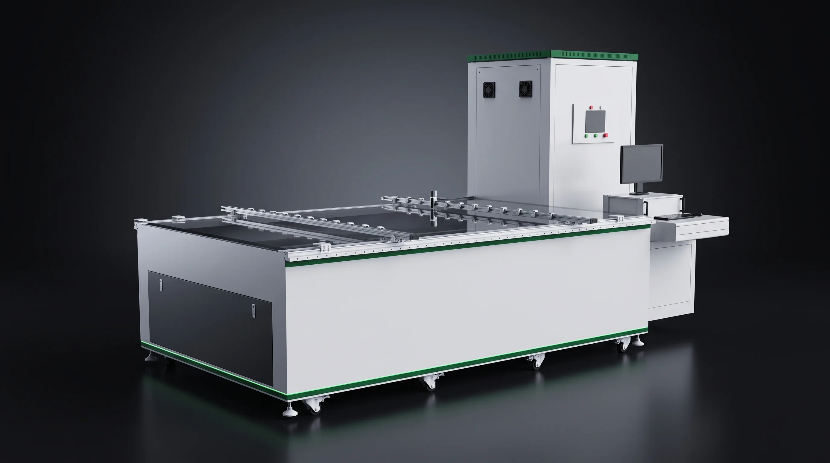
Stringer output end docked to the robotic layup station on a solar panel production line
Where it docks, we ask for the layup machine height and dimensions in advance.

What the floor plan has to allow

Turn
Cells arrive short edge first, the laid-up panel leaves long edge first, so the machine turns travel by 90 degrees rather than passing straight through
Clearance
A door access system or fencing, which makes the space to clear larger than the machine outline
Docking is designed in, not adjusted afterwards. The SML-S60 can dock to a layup machine or run as a standalone station, and where it docks we ask for the layup machine height and dimensions in advance. Ask for both heights on both machine drawings — 1230 mm at the stringer interface and 950 ±50 mm at the glass interface — and confirm the glass conveyor height of the line you already run.

Stations 04 and 05

Bussing, EL and IV Testing

Bussing is where the strings stop being separate circuits. Testing rejoins the flow after lamination, on the far side of your framing line.

Automatic bus bar welding machine joining string ends into the module circuit
The SML-B200 joins the string ends into the module circuit. The panel that leaves it has its complete electrical layout in place, ready for the laminator.
The output of these two stations is a measurement record as much as a panel — the document your quality team files, and the one your own customers ask to see for a batch.
Which IV tier a line takes follows from the module class you build — a station-level choice made once the module design is fixed. Confirm whether your floor tests before framing or after it: that decides the order of the last two stations.
EL inspection station for laminated crystalline-silicon modules
SML-E EL inspection, run once the panel comes back from lamination.
Module IV tester, lower power tier of the same test station
SML-T450 First of three power tiers of one IV station.
Module IV tester, middle power tier of the same test station
SML-T500 Middle tier, same station, same position in the flow.
Module IV tester, upper power tier, with the BIPV version alongside it
SML-T1000 Upper tier. The SML-T-BIPV covers building-integrated modules.

Station 06

Frame Marking at the Line Exit

A floor question rather than a process one: whether your framing line has a slot that can be opened up, or whether marking is added beside a line that stays as it is.

Ask your framing line supplier whether that break is possible, and send the answer with the layout.

Inline frame marking machine sitting in the conveying line as a station of its own

Inline, a station of its own

Model
SML-M200 inline frame marking machine
Joins by
A slot in the conveying line
Needs
A conveyor break at marking height
External frame marking machine hanging alongside a continuous framing line

External, beside the line

Model
SML-M150 external frame marking machine
Joins by
Hanging alongside the line
Needs
Nothing opened up — for continuous framing lines

One frame or six

Combined Machines Against Split Stations

Three machines combine steps that otherwise sit in separate frames. The SML-I150 puts scribing and stringing into one machine. The SML-I150L puts scribing, stringing and layup into one machine. The SML-L150 combines layup and welding in one frame.

SPLIT ROW · SIX FRAMES SCRIBE STRING LAYUP BUSS TEST MARK Five joins — each a transfer, a docking height, floor length and an acceptance run COMBINED ROW · FOUR FRAMES SML-I150L · SCRIBING + STRINGING + LAYUP BUSS TEST MARK Three joins — the frame carries the rest on its own internal transport
What combining takes out of the line is the handoff itself.

Swipe the diagram

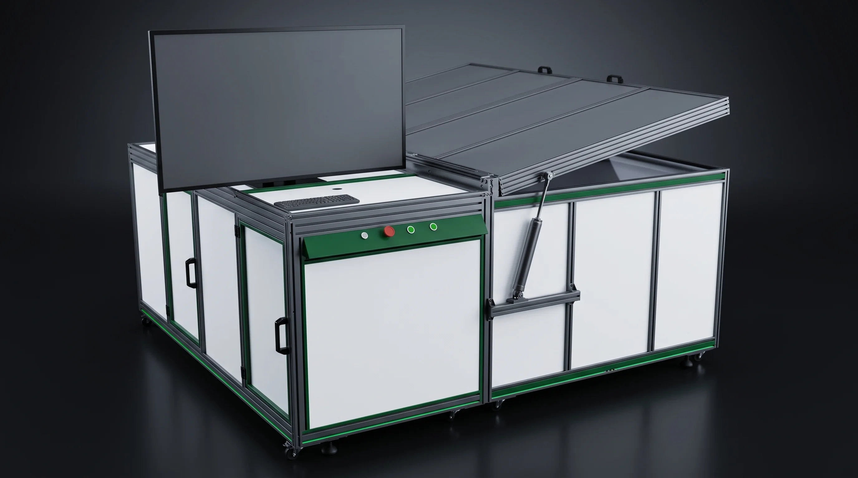
Combination machine carrying layup and welding inside one frame

What combining concentrates

Every join between two frames is a magazine or conveyor transfer, a docking height to agree, a transfer section to build and a length of floor to give it. Those disappear when the steps share one frame and one internal transport.

  • One tooling set covering the combined steps
  • One maintenance window for all of them
  • One acceptance run over the whole sequence rather than a station at a time

That suits a floor built around a single stable cell format and module size, running at steady volume, where the format is not expected to move for the life of the equipment.

Split station standing on its own, sized to drop into a row that is already conveying

Where split stations fit better

Build the whole row from combined frames and there is no slot left to drop a station into later, so adding a scriber or a second stringer means re-planning the row instead of extending it.

  • More than one cell format — retooling takes out one station, not a sequence
  • Capacity added in steps — a faster station goes in at the point that limits output
  • One aged machine replaced — a drop-in station only has to match the string length and docking heights already in use
  • One station down — the others keep running through their buffers
SML-I150L combination machine carrying scribing, stringing and layup inside one frame
One frame, one tooling set, one acceptance run — and three of the six joins gone with it.
Two questions settle it on a quoted list. Ask which of the six process steps sit inside the frame on any machine quoted to you, and ask how many separate technical agreements and acceptance runs the resulting line carries. A shorter row with fewer interfaces is also a row with fewer places to put a different machine later.

Arithmetic, not a package

Throughput Matched Station by Station

A split row lets throughput be matched station by station rather than taken as a fixed set. The tiers exist so you can lift the one station that limits output, without buying speed you have nowhere to use.

Every figure below comes from the parameter table of a technical agreement, not from a summary sheet.

SML-C72Scribing
4800 BC / 6800 TOPCon and PERC
SML-S60Stringing
4800 BC half cells an hour
SML-S40Stringing
3400 at 3–12BB / 3200 at 13–20BB
SML-C20Scribing
1600 full cells an hour or better
SML-S15Stringing
1100 half cells an hour
Bars share one scale, 0 to 6800 pieces an hour, and the SML-C72 bar carries both of its figures.
Read two rows together. An SML-C72 feeds an SML-S60 without either waiting. Put an SML-S15 behind that same scriber and the row runs at 1100 an hour.
Row of machines on a solar panel production line, each station sized against the one before it
1 The slowest station sets the line. Ask which station on a quoted list is the slowest, take its hourly figure from the parameter table rather than a summary, then ask what lifting only that one would cost. One scriber, two throughput figures

Give us the cell drawing, the busbar count, the string length and the module dimensions, and a station list with a layout proposal comes back within 24 hours.

Start a layout

Before the drawing is issued

Interfaces and Services on One Drawing

Service entries go on the same drawing as the interface quantities rather than being left to site — which is what keeps an entry from landing behind a machine that has to be moved to reach it.

Interface quantityWhat it fixesWhere it is judged
String lengthModule length, and how far the string reaches into the layup windowRun-off against the blueprint format
Cell pitchHow many cells a string of that length carriesParameter table, ±0.3 mm on the SML-S60 and SML-S15
String spacingHow the strings fill the module across its widthLayup parameter table, 1 to 10 mm
Stringer to layup dockingThe join between the two main framesBoth machine drawings, 1230 mm
Glass entry and exitThe join between your glass line and oursBoth machine drawings, 950 ±50 mm

Swipe the table

EXHAUST · ROOF SIDE POWER · 380 V 50 Hz FIVE-WIRE COMPRESSED AIR · 0.6–0.8 MPa 01 02 03 FLOOR · 600 kg/m² OR BETTER SERVICE ENTRIES PLACED AT DRAWING STAGE
Four service entries, marked on the plan alongside the machines that need them.

Swipe the diagram

The same drawing carries the roof-side exhaust openings each station needs. Utilities and layout has the figures station by station.
Straight-run solar panel production line laid out with its service entries marked at drawing stage
Ask for the layout drawing with the interface quantities marked on it, then check the docking heights against the machines already installed on your floor.

Six models, six agreements

Machines on This Solar Panel Production Line

Six models cover our span, and every parameter quoted for them comes from a full technical agreement. Your side of the floor keeps the laminator, the framing machine, the cleaning machine and the junction box station.

Everything upstream of the tested cell — ingot, wafer and cell equipment — sits outside this span too.

SML-C72 lossless laser scriber, first station on the solar panel production line
SML-C72 Scribing

Lossless laser scriber

4800/h on BC full cells, 6800/h on TOPCon and PERC in dual line, breakage 0.05 percent.

Full parameter table
SML-C20 entry laser scriber on a 1000 by 650 mm footprint
SML-C20 Scribing

Entry laser scriber

1600 full cells/h or better, 40 micron kerf, 400 kg on a 1000 by 650 mm footprint.

Full parameter table
SML-S60 BC tabber stringer feeding the layup station at 1230 mm
SML-S60 Stringing

BC tabber stringer

4800 BC half cells/h, 20 ribbon feeding motor sets, string length 540 to 1400 mm.

Full parameter table
SML-S40 multi-busbar stringer for TOPCon and PERC half cells
SML-S40 Stringing

Multi-busbar stringer

3400/h at 3 to 12 busbars, 3200/h at 13 to 20 busbars, string length to 1400 mm.

Full parameter table
SML-S15 entry stringer with 12 ribbon feeding motor sets
SML-S15 Stringing

Entry stringer

1100 half cells/h, 12 ribbon feeding motor sets, pitch accuracy ±0.3 mm.

Full parameter table
SML-A6 robotic layup station where strings and glass meet on the solar panel production line
SML-A6 Layup

Robotic layup station

6 s or better per string, module window 1650–2500 by 990–1450 mm, CCD located.

Full parameter table

Paste this into an enquiry

Inputs for a Solar Panel Production Line Layout

Everything below can be pasted straight into an enquiry, and it is enough for a station list and a first layout to come back.

A missing item does not stop the enquiry — it moves that one decision to the second reply.

From the cell

  • Cell type — BC, TOPCon or PERC
  • Cell size between 156 and 220 mm, and thickness
  • Busbar count, 3BB to 20BB, and whether you expect to reach 25BB later
  • Target string length and cell pitch, or the module drawing behind them
  • Module length and width, cells and strings per module

From the floor

  • Clear height, floor load
  • Glass conveyor height already running
  • Docking height of your laminator
  • Where power and air enter the building, and the roof-level exhaust route
  • If a row exists, its string length and docking heights

From the project

  • Your output target
  • A new line laid out on a new floor
  • A BC upgrade to a running TOPCon or PERC floor
  • A single station going into an existing row
After a contract is signed, the cell drawing is signed off by you and production cell and string information reaches us within 5 to 10 working days, so tooling is cut against the format the line will actually run. Acceptance then runs against the parameter table of each technical agreement, with operator training completed before it is signed.

Start your line layout

Cell Drawing, Busbar Count, String Length

Put those three, the module dimensions and your floor plan in one message, and the station list with interface heights marked reaches you within 24 hours.

What comes back
Station list, layout proposal, both docking heights marked
For one station
String length in use and the height the existing row hands over at

How to reach you

[email protected]