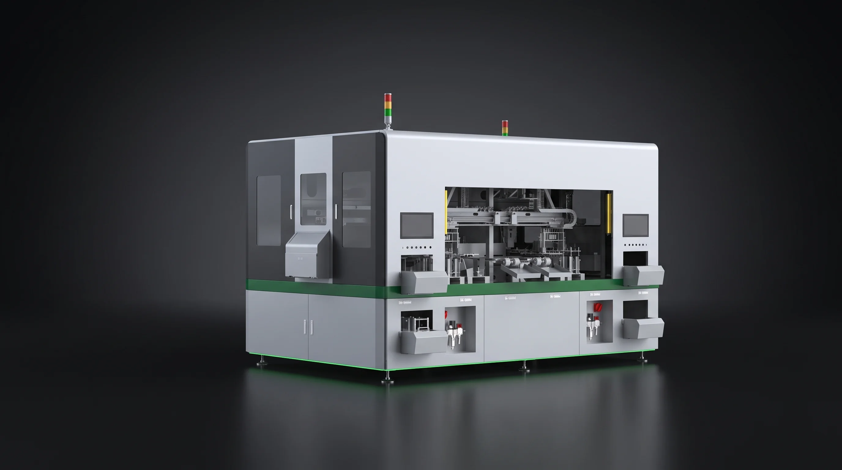
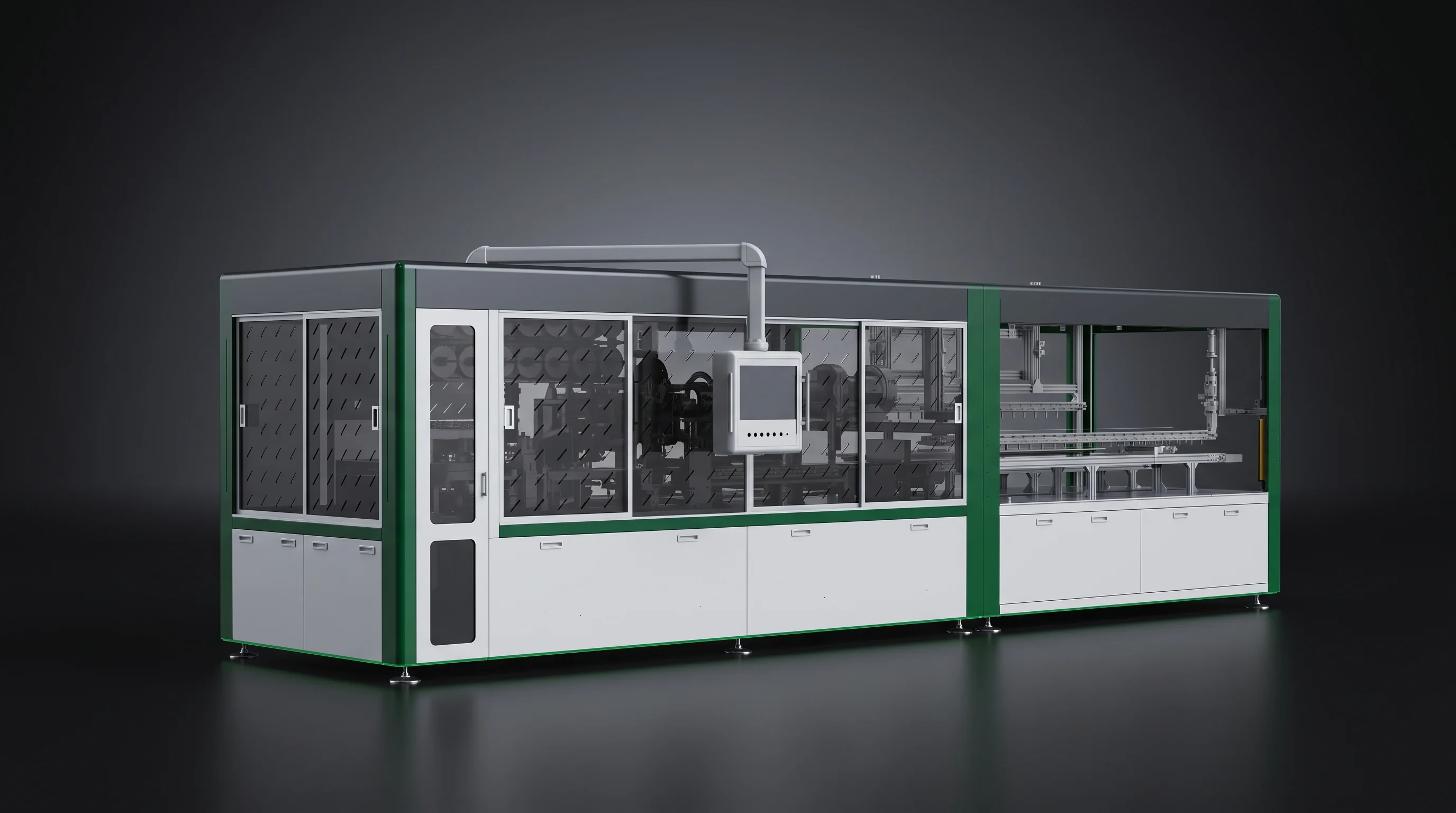
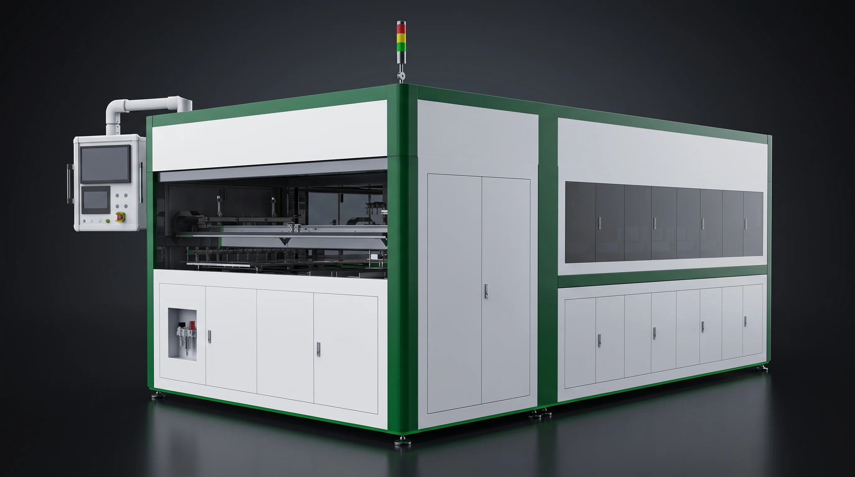
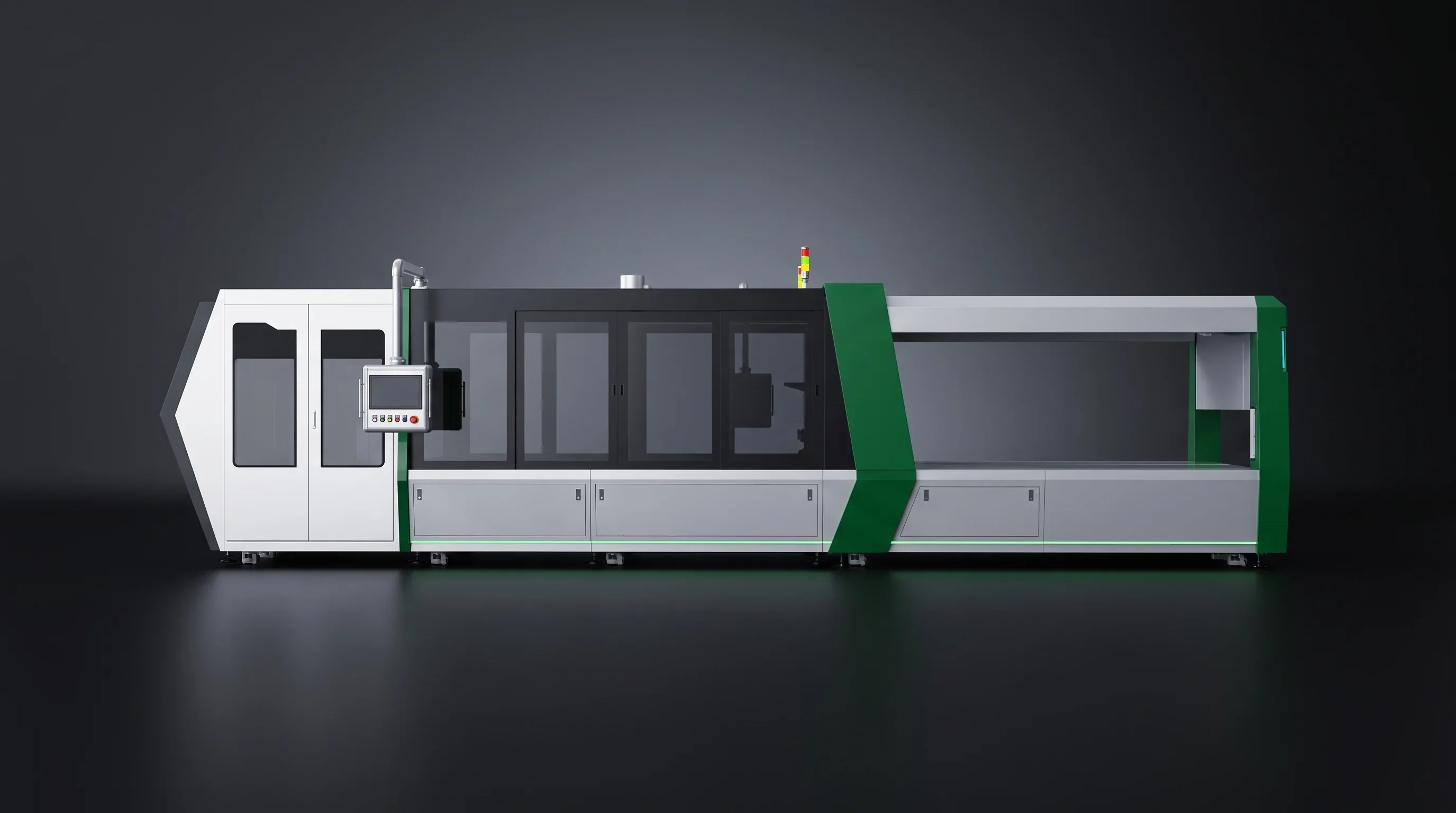
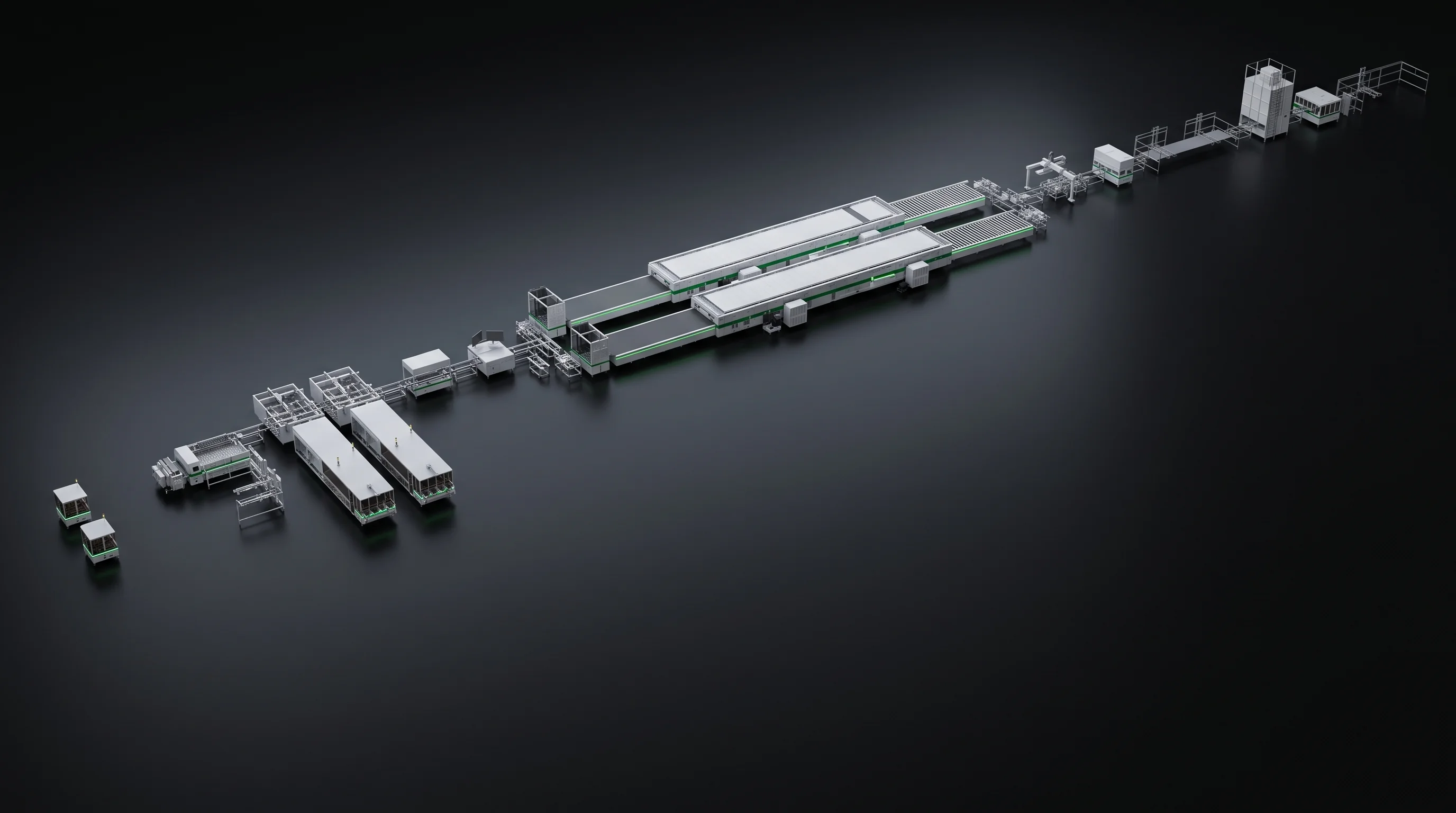
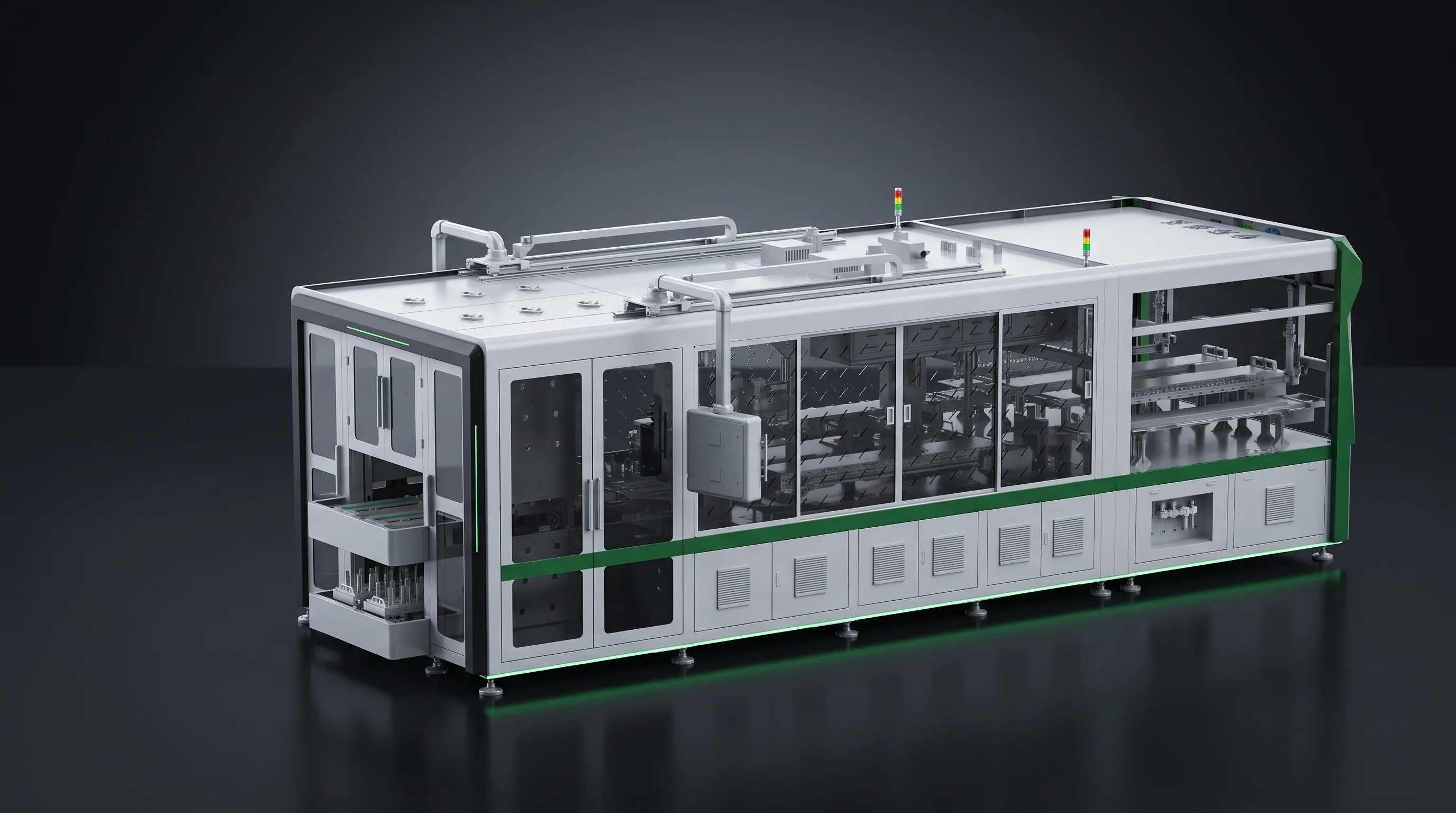
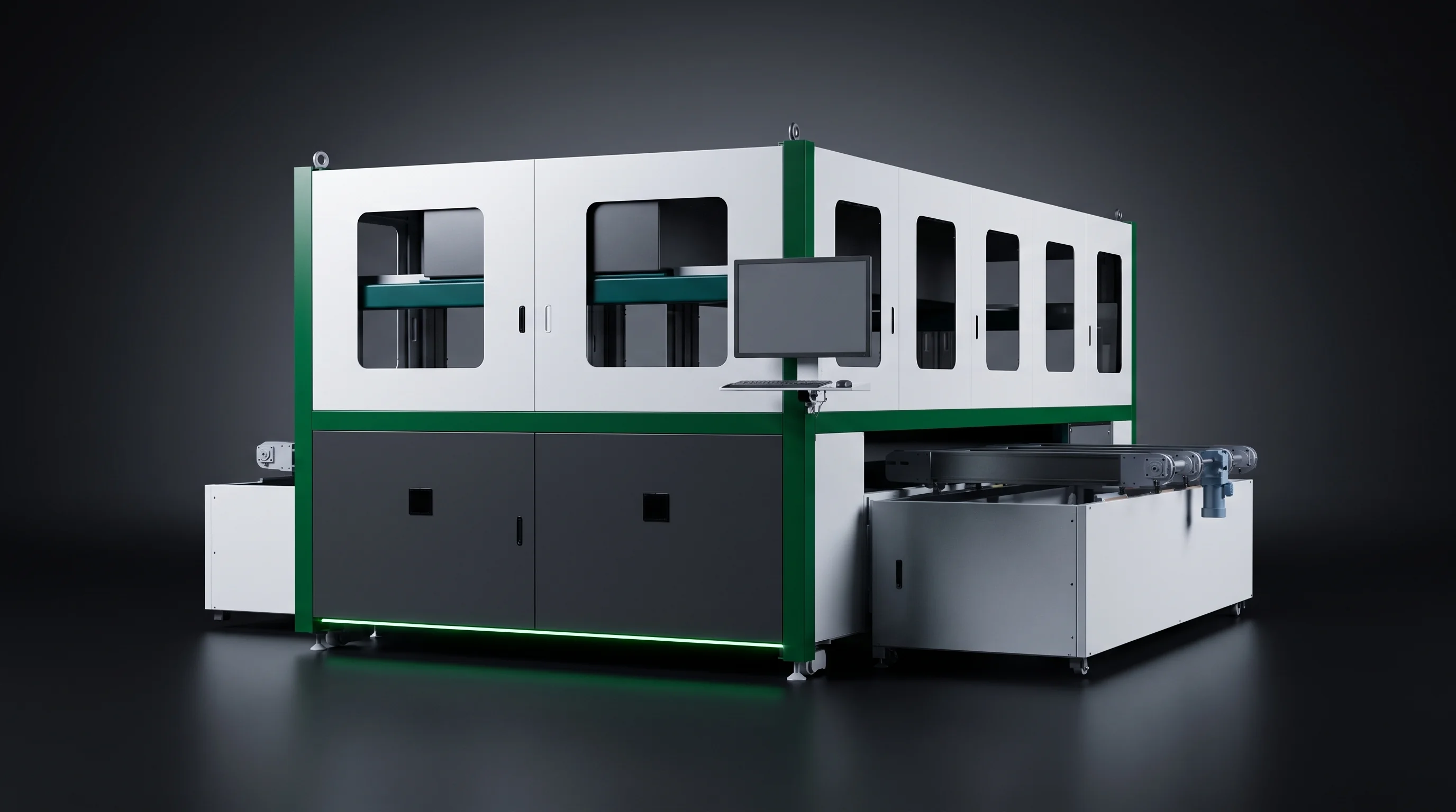
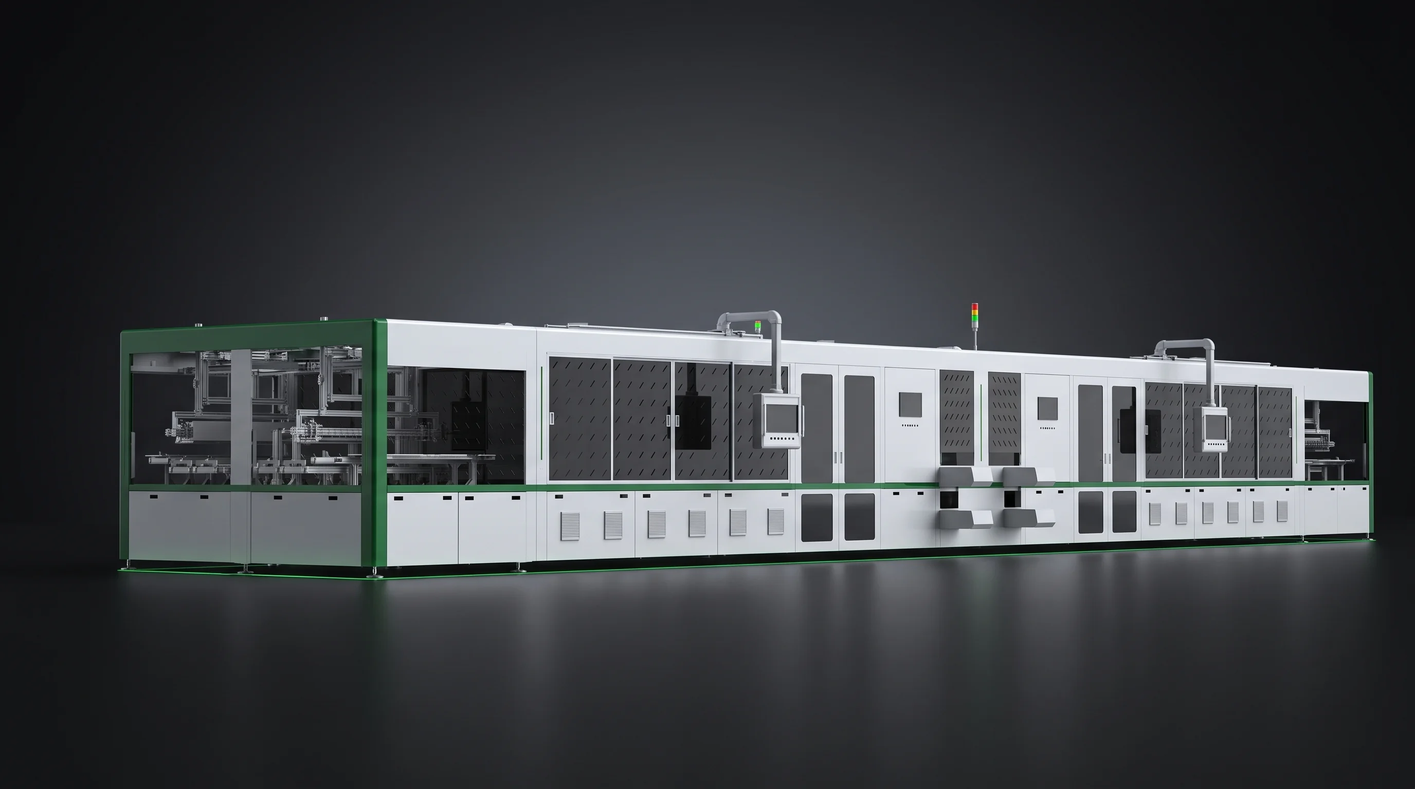
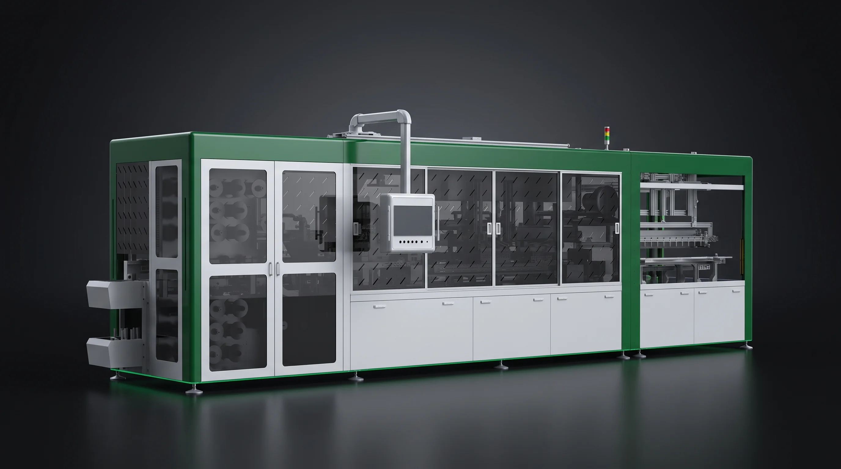
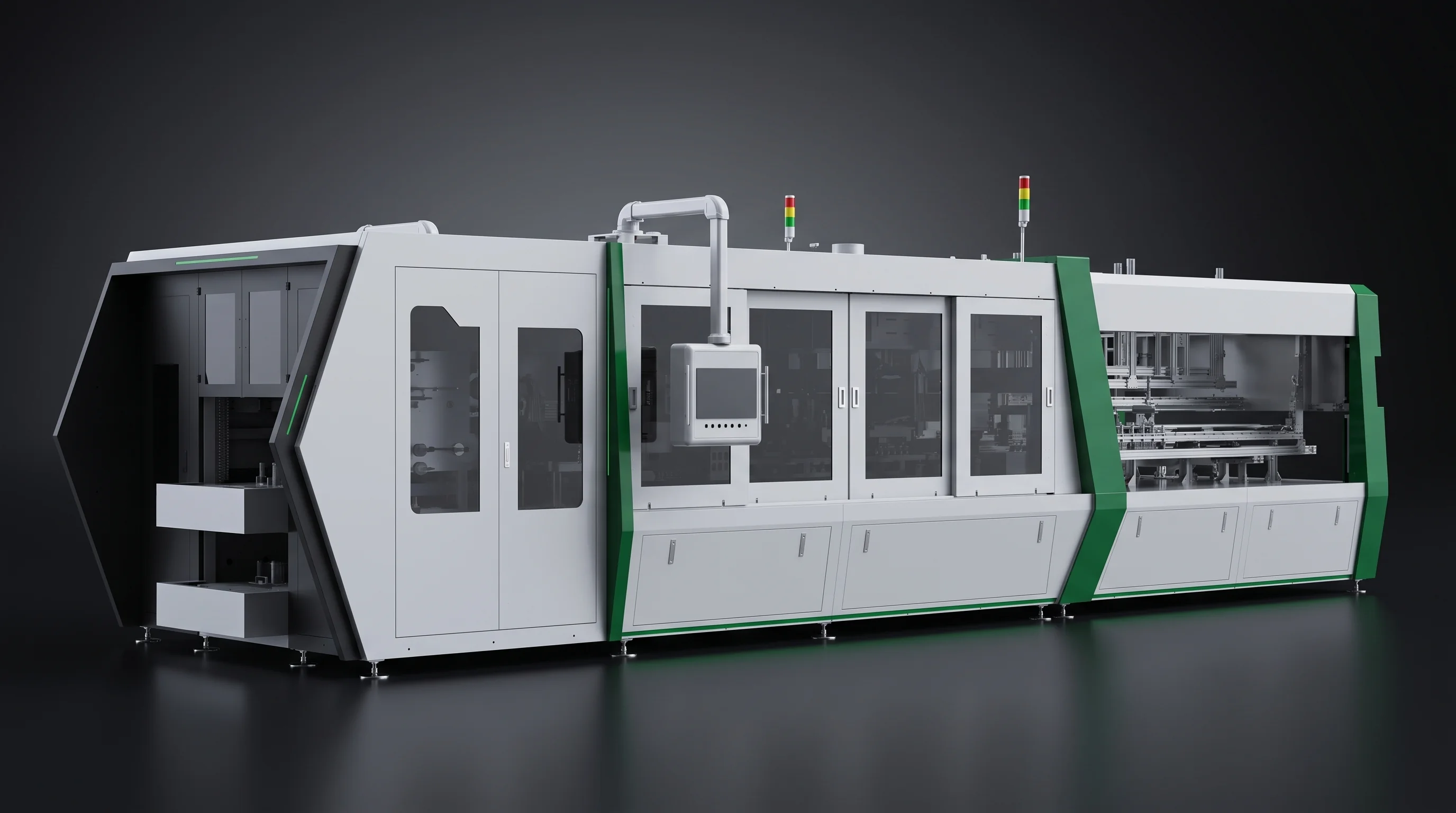
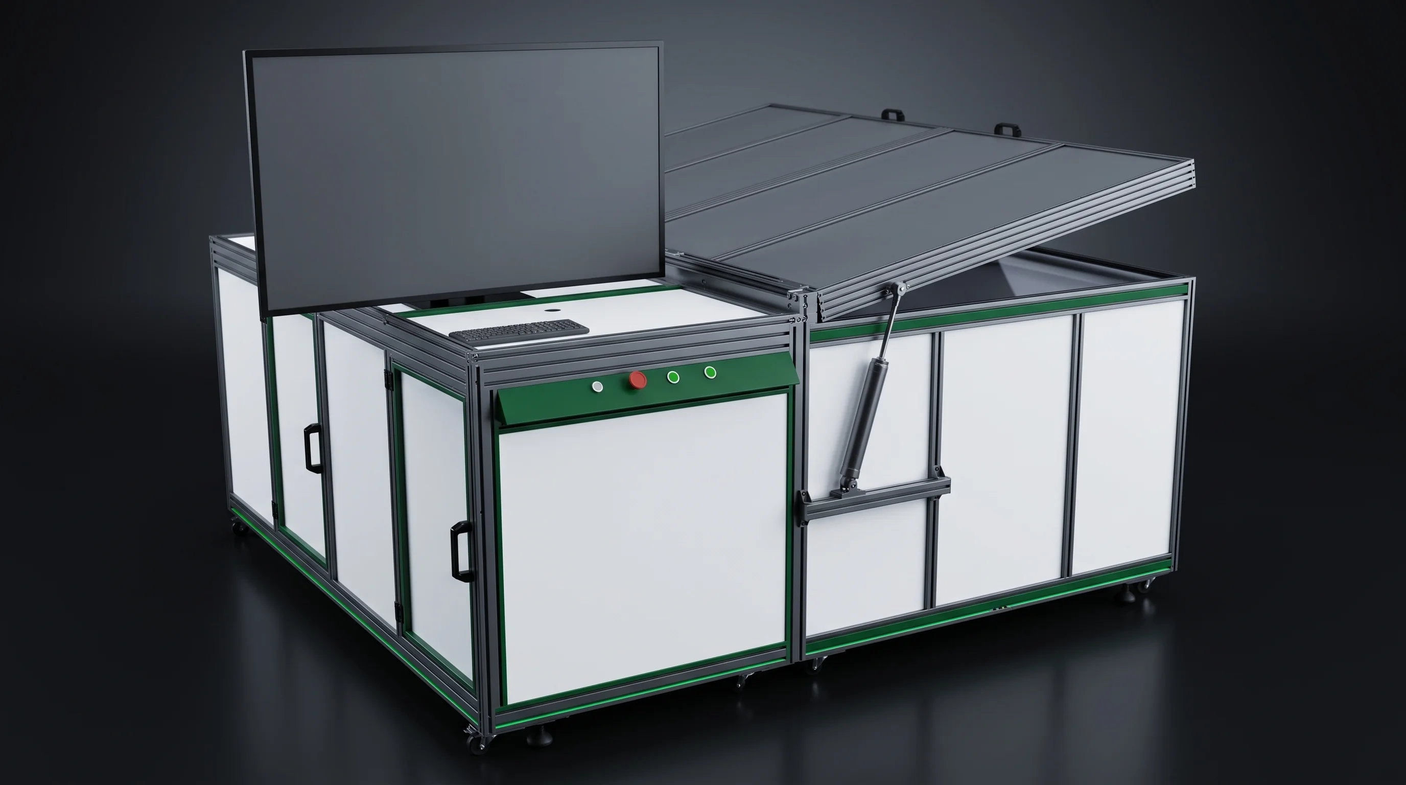
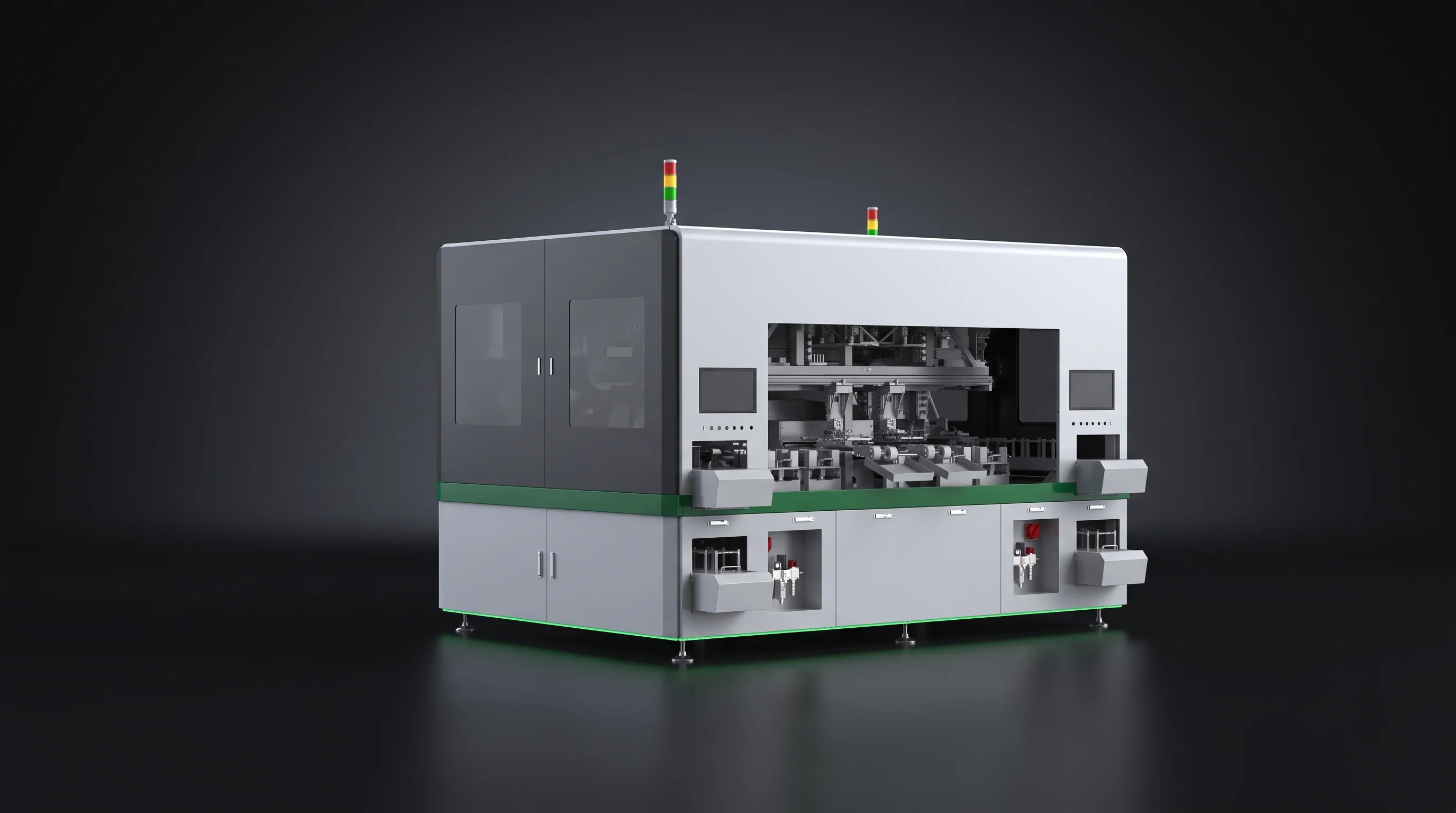
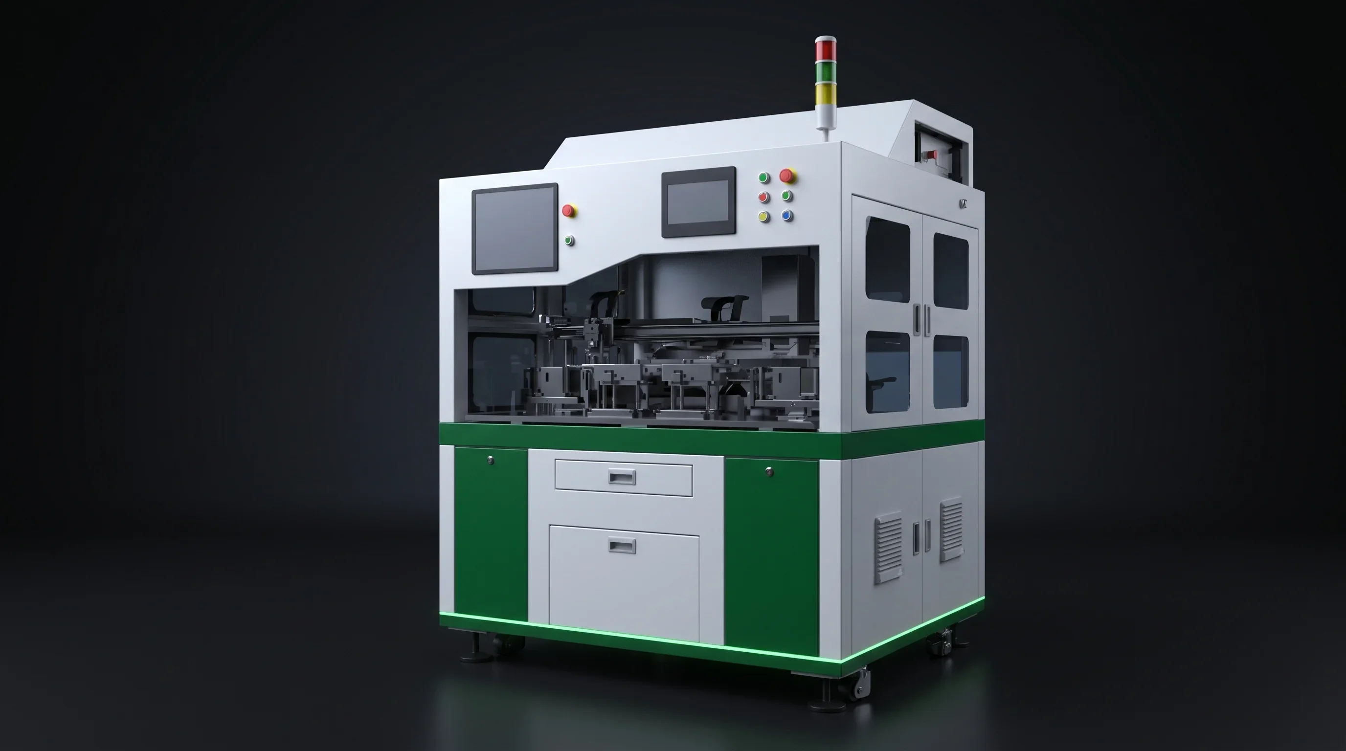
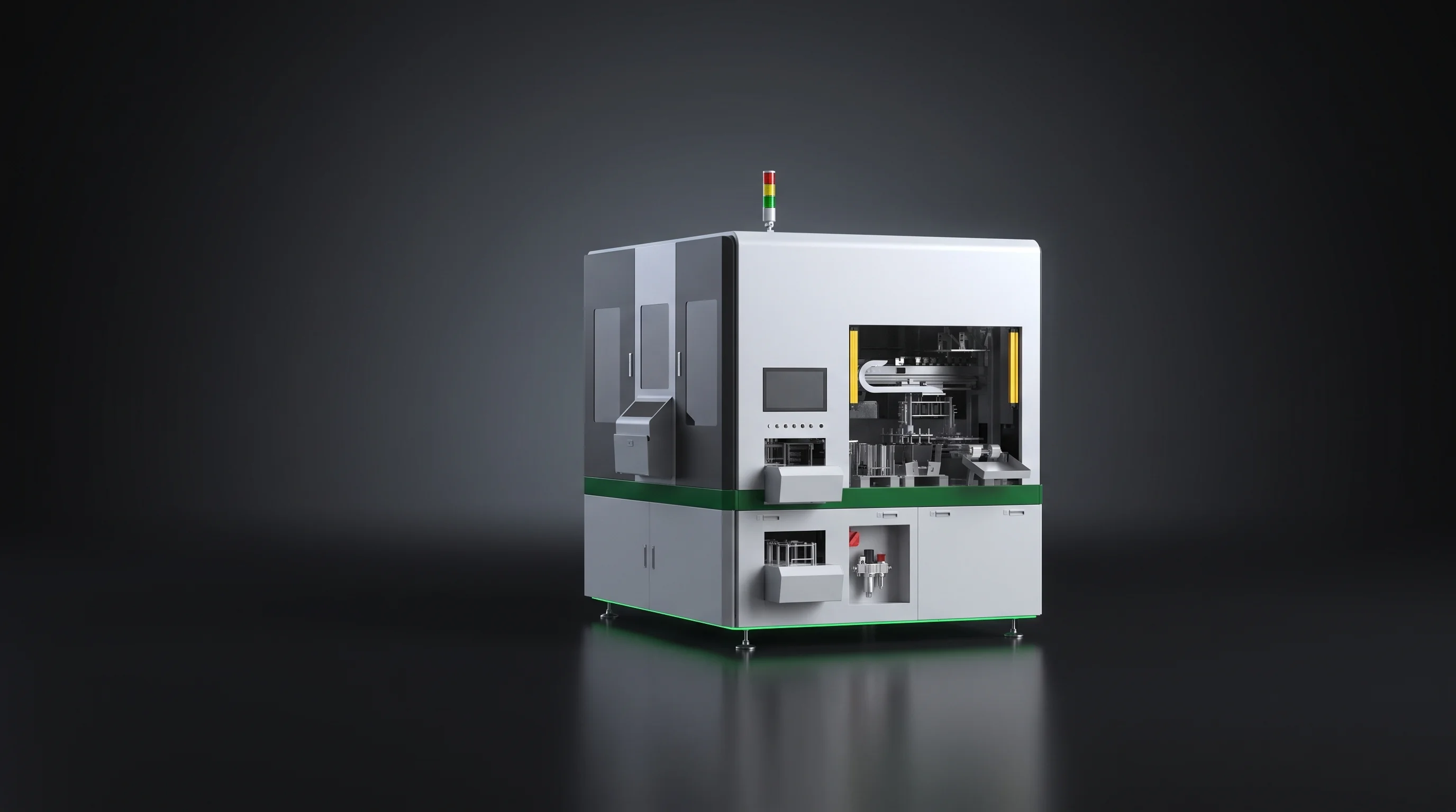
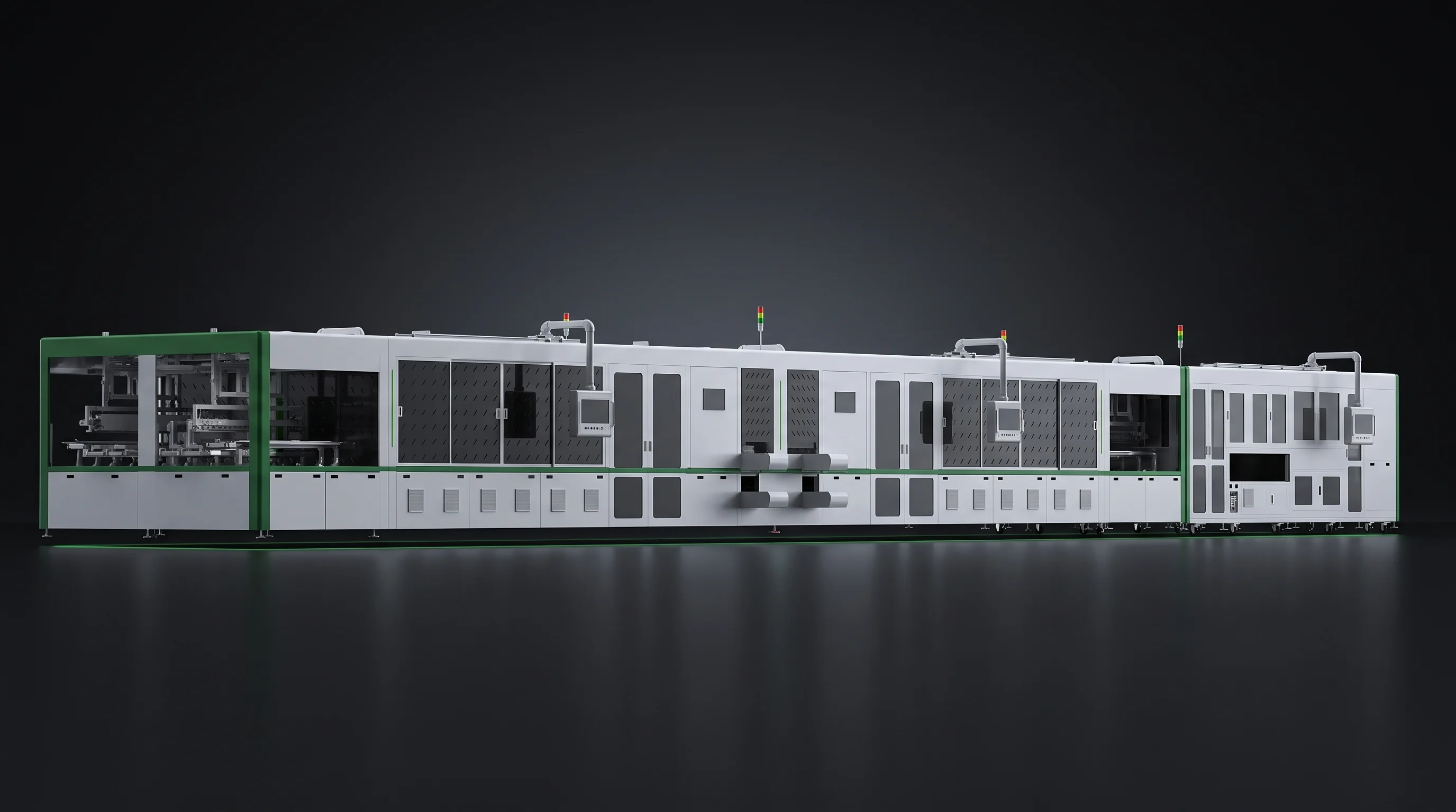
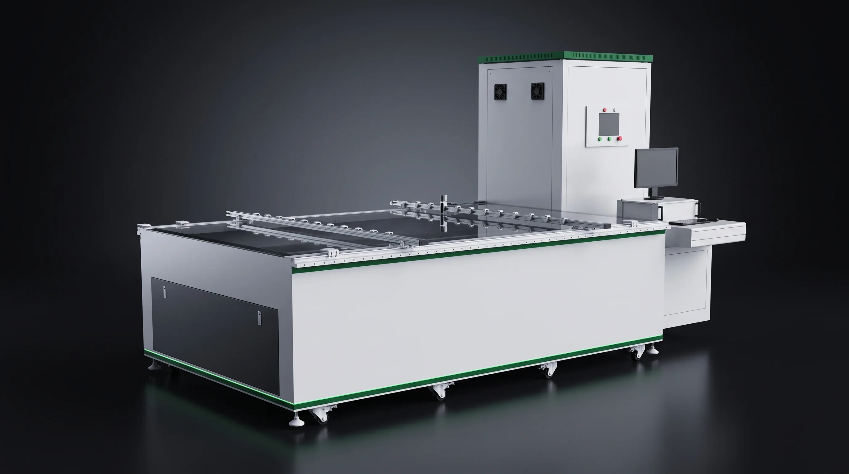
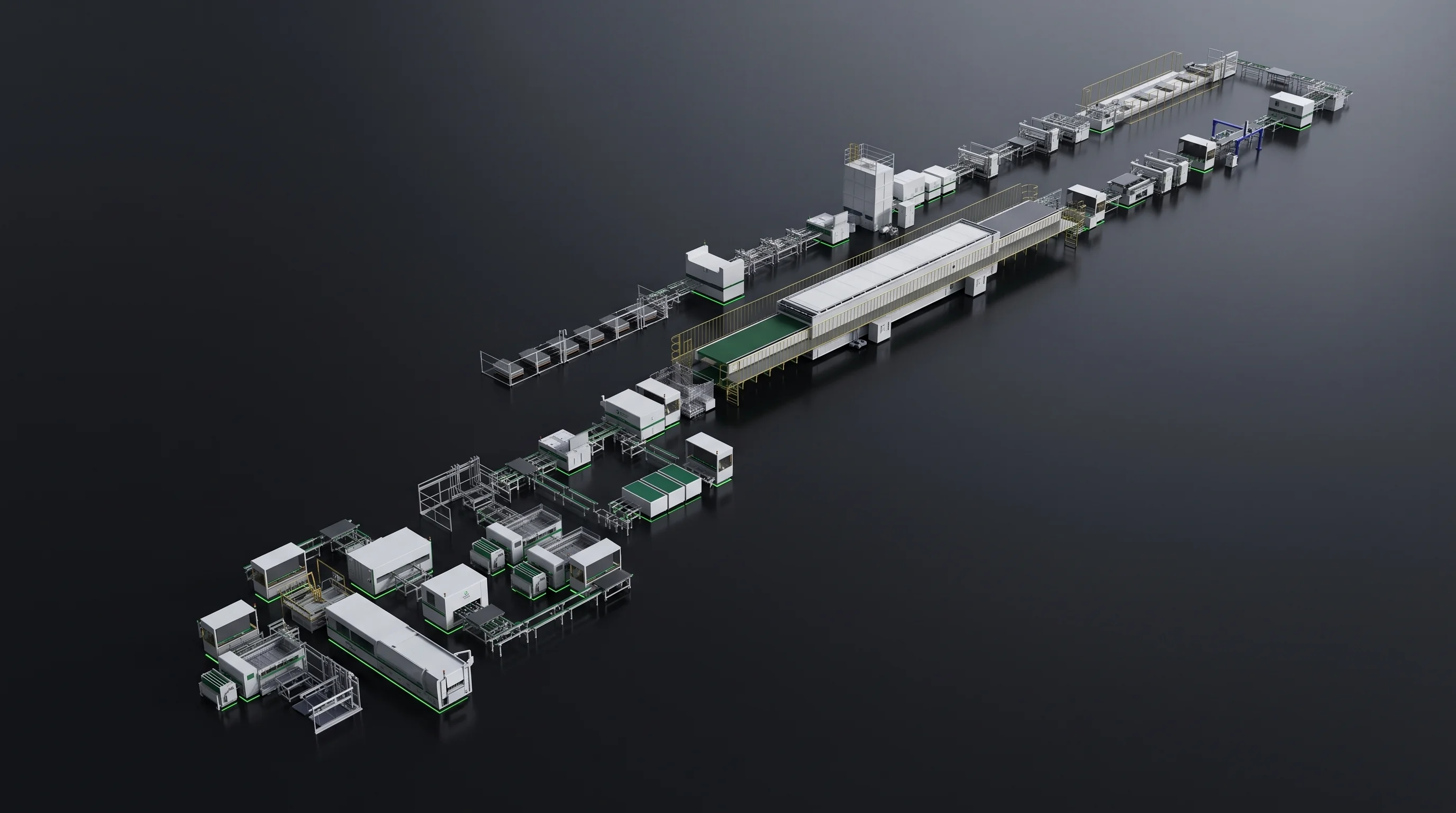
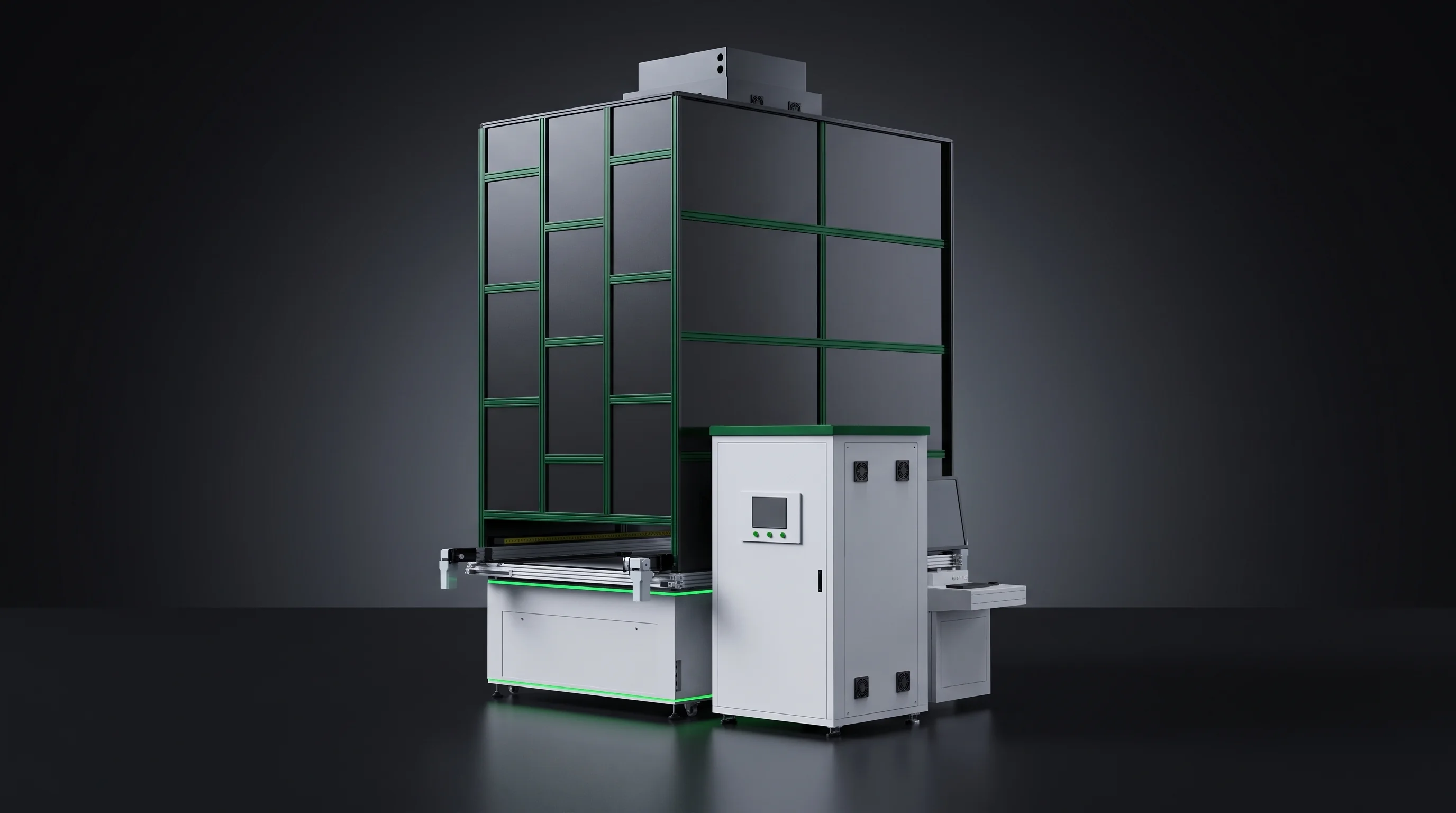
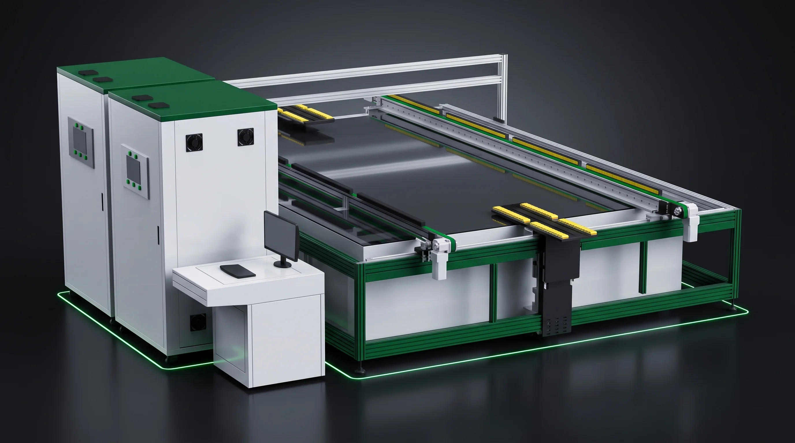
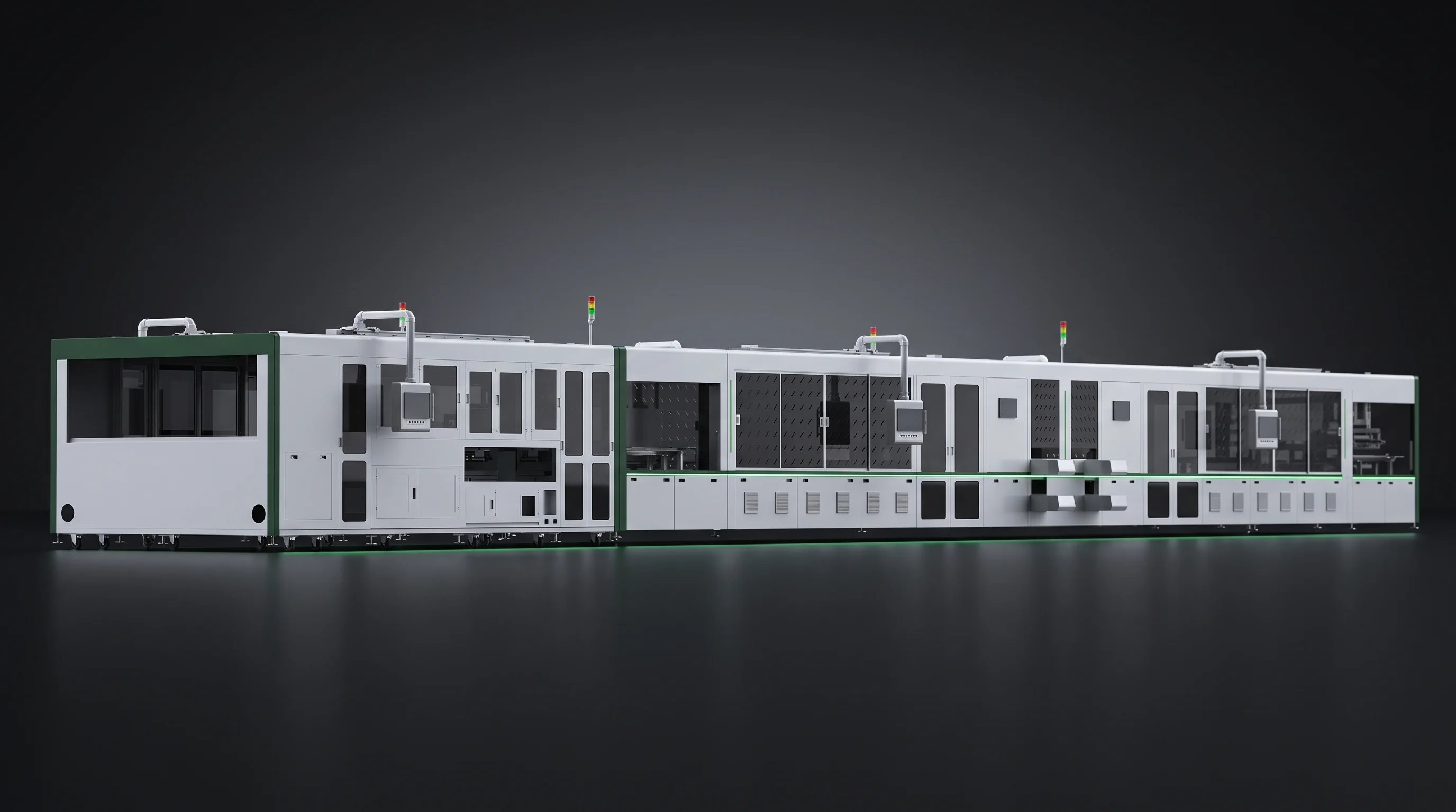
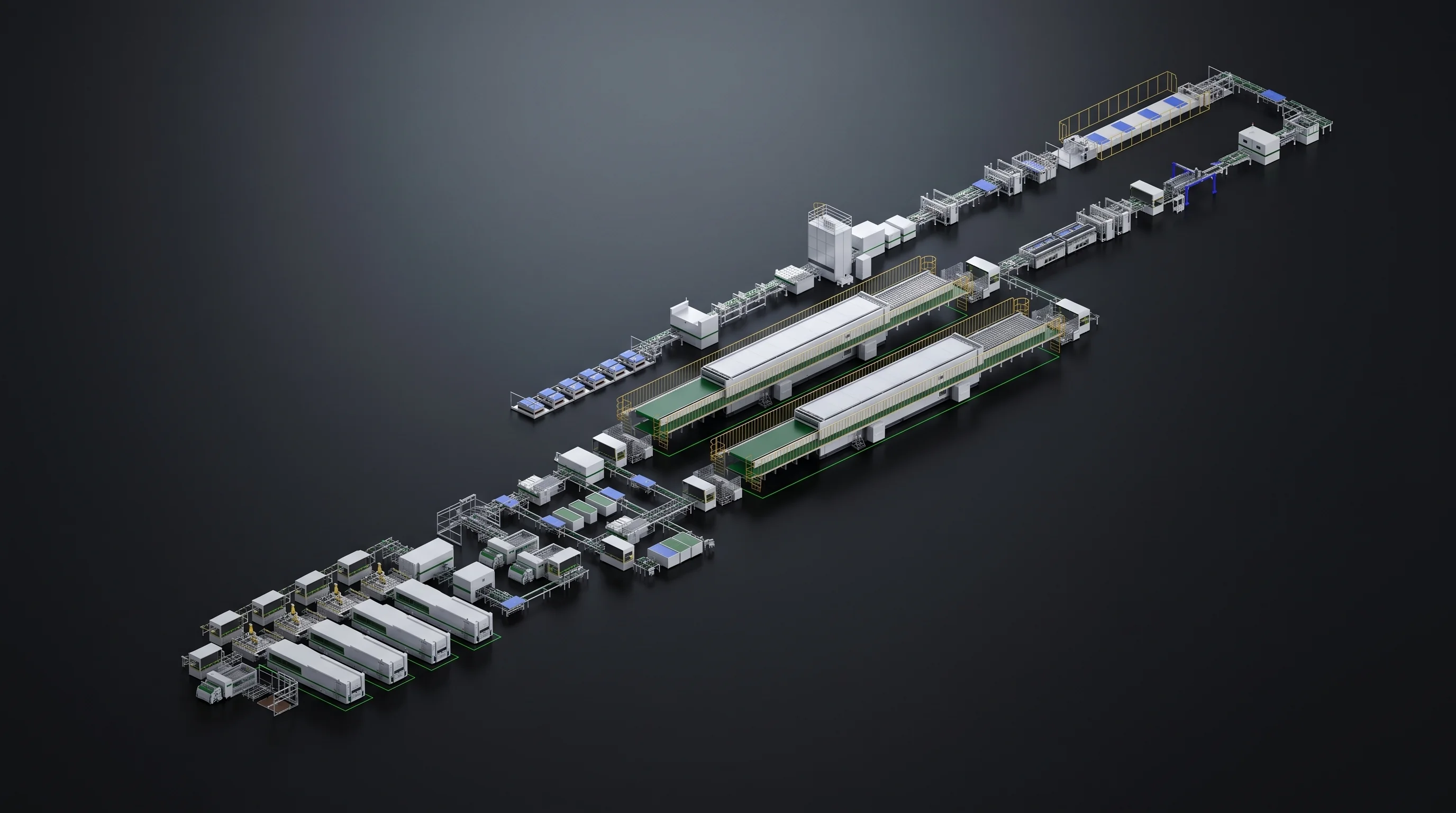
U-shaped solar module production line on a plant floor, the row whose module line cell compatibility is the overlap of its machines
Widest machine window Line window Cell size square cell, mm 166 – 210 156 220 Thickness microns 120 – 200 110 220 Busbar count grid lines per cell 3BB – 20BB 3BB 25BB Narrowest figure in the row sets each axis. Tooling is checked separately.

Cell compatibility and changeover

Module Line Cell Compatibility and Changeover

What one machine can run, its parameter table states. What your line can run next Monday is the overlap of every machine standing in the row and the tooling actually sitting in your building. This page works through the distance between the two.

  • 6 machine windows
  • 1 line window
  • 7 rows read again after a change

How a line window is formed

Module Line Cell Compatibility as an Overlap

A machine window is a property of one machine. A line window is arithmetic. Every cell passes through every station in the row, so the format your plant can run is the overlap of the windows of the machines standing in it, and on each axis the narrowest figure in the row sets the line.

The chart is drawn from the six parameter tables in our own range. Change one model in one position and the green band moves with it.

LINE WINDOW 166 – 210 mm SML-C72 laser scriber 166 – 210 SML-C20 entry scriber 156 – 220 standard two-cut set tooled to your drawing SML-S60 BC stringer 166 – 210 SML-S40 multi-busbar stringer 166 – 210 SML-S15 entry stringer 166 – 210 SML-A6 robotic layup sets the module outline, not the cell edge 150160170 180190200 210220230 Cell edge dimension, mm
Six cell size windows on one axis. Only the SML-C20 reaches outside the band, and standing in this row it reads 166 to 210 like everything else.
Swipe the chart
Thickness
120 – 200 µm

Higher floor, lower ceiling

A line of SML-C72, SML-S40 and SML-A6 reads 120 to 200 micron, because the scriber runs 120 to 220 and the stringer 110 to 200. The 110 micron figure reaches the line only where cells arrive already cut and the row starts at the stringer.

Cell size
166 – 210 mm

The tooling narrows it again

The SML-C20 takes 156 by 156 to 220 by 220 mm, wider than anything else in the range, and standing with stringers that take 166 to 210 the line reads 166 to 210. Inside that band its standard cleaving tooling covers 166 to 182 mm two-cut work.

Busbar count
3 – 20BB

One model sets the ceiling

All three stringers cover 3BB to 20BB, and the SML-S60 and the SML-S40 step to 25BB. A line built around the SML-S15 carries a ceiling of 20BB even though the stations around it would take more.

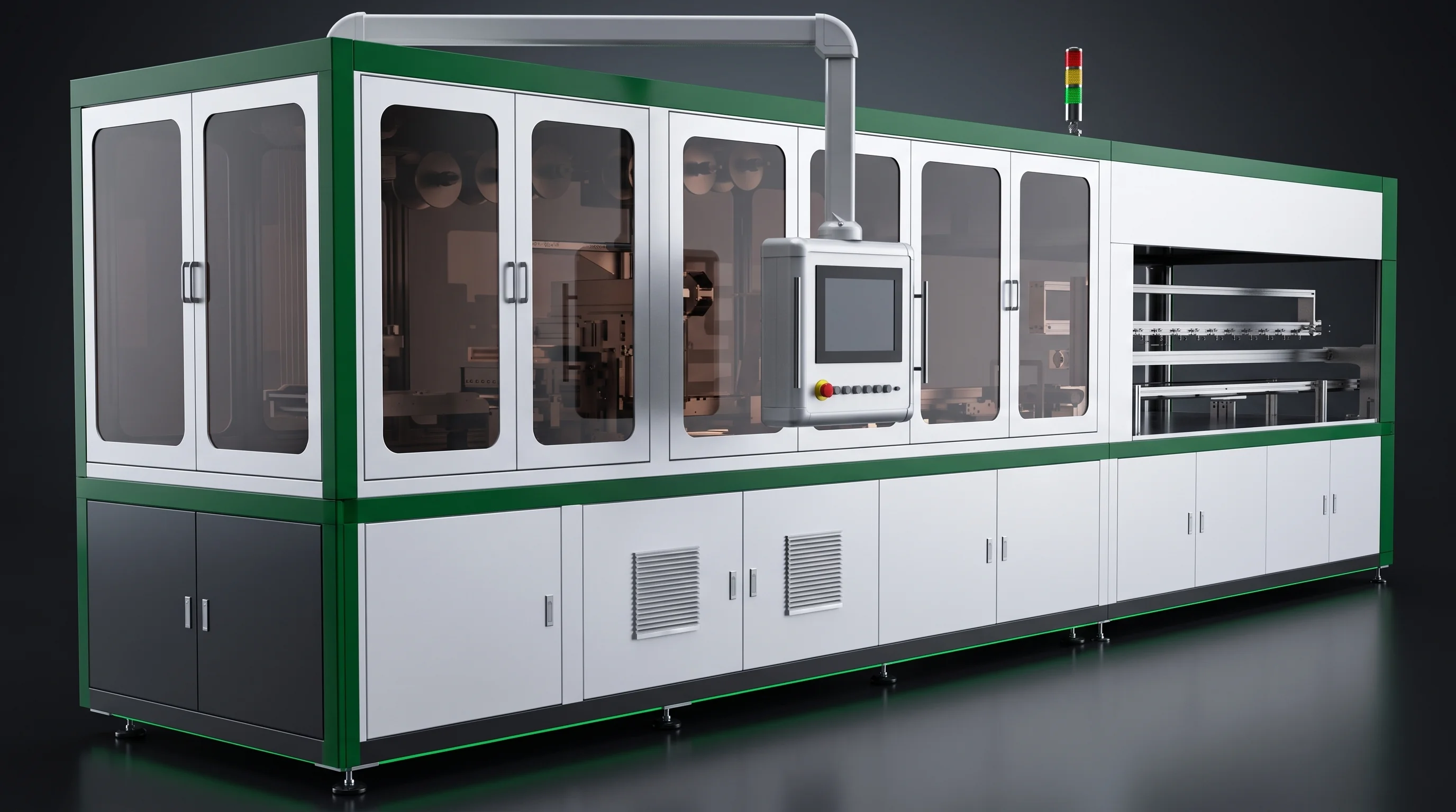
Straight-line module assembly row under studio light, every station in it narrowing the line window
Every station in the row is in the arithmetic. Take one out and the window changes shape.

Machine by machine

Six Windows That Set Module Line Cell Compatibility

Each machine constrains a different axis. Reading six separate windows rather than one range is what makes a format decision safe, and it is the difference between a line that runs your second format and a line that stops for it.

Open a card for the window as its own parameter table states it. Every figure here is a row the machine is accepted against.

SML-C72 laser scriber, the head of the line that sets module line cell compatibility on size and thickness

Head of the line

SML-C72

Constrains size and thickness. Busbar count it does not constrain, because grooving and thermal cleaving work on the cell body.

Window as stated
Cell size
166×166 – 210×210 mm
Thickness
120 – 220 µm
Cut
standard two-cut
Busbar count
not constrained
SML-C20 entry laser scriber with its cleaving station open

Widest size window

SML-C20

Constrains what its cleaving tooling was made for rather than what the optics can reach.

Window as stated
Cell size
156×156 – 220×220 mm
Thickness
120 – 220 µm
Batch deviation
10 µm
Table
226 × 226 mm
SML-S60 back contact stringer seen from the infeed side

BC stringing position

SML-S60

Constrains cell size, thickness, grid count, string length and cell pitch at once, including pitch below zero.

Window as stated
BC cells
166 – 210 mm
Thickness
110 – 200 µm
Busbar count
3BB – 20BB, 25BB expandable
String length
540 – 1400 mm
Cell pitch
−1 to −0.5 mm, 1 to 5 mm
SML-S40 multi-busbar stringer with its magazine groups in view

Volume stringing position

SML-S40

Constrains the TOPCon and PERC position at volume, and carries the lowest thickness floor in the range.

Window as stated
Half cells
166 – 210 mm
Thickness
110 – 200 µm
Busbar count
3BB – 20BB, 25BB expandable
Cell pitch
1 – 5 mm
String length
to 1400 mm
SML-S15 entry stringer, the model whose window sets a 20BB ceiling on the line

Entry stringing position

SML-S15

Same position at entry rated output, and the model that raises the thickness floor and caps the grid count.

Window as stated
Half or third cells
166 – 210 mm
Thickness
120 – 200 µm
Busbar count
3BB – 20BB
Cell pitch
1 – 5 mm
Robotic layup and bussing station laying strings onto glass

Layup position

SML-A6

Constrains the module rather than the cell, which is why a cell change still has to be checked here.

Window as stated
Module length
1650 – 2500 mm
Module width
990 – 1450 mm
String spacing
1 – 10 mm

The axis that gets misread

Thickness Floors, Machine by Machine

LINE WINDOW 120 – 200 µm SML-C72 120 – 220 SML-C20 120 – 220 SML-S60 110 – 200 SML-S40 110 – 200 SML-S15 120 – 200 100120140 160180200 220 Cell thickness, microns
Two different floors in the same range: 110 micron on two stringers, 120 on the third and on both scribers.
Swipe the chart

The thickness floor of a line is a machine difference, and it is worth saying flatly because it is regularly read as a route difference.

  • 110 – 200 µm on the SML-S60 and on the SML-S40 alike
  • 120 – 200 µm on the SML-S15
  • 120 – 220 µm on both scribers

Nothing in that list follows from whether the line is BC or TOPCon and PERC. It follows from which model stands in which position, which is why a row carrying an SML-S15 reads a 120 micron floor and one carrying an SML-S40 with pre-cut cells reads 110.

The breakage figure carries its own condition

Stringing holds breakage at 0.25 percent or better on A-grade cells, measured at 120 micron and above on the SML-S60 and the SML-S15, and at 110 micron and above on the SML-S40. So the SML-S60 runs to 110 micron, and the figure it is accepted on is stated at 120 and above. Below that the machine keeps running and breakage rises, which is a thing to know before the order rather than at acceptance.

SML-S60 stringer welding section, where thin cells decide the breakage condition
Thin cells do not change the window. They change the condition the window is judged under.
Two module assembly rows standing side by side under studio light

Send the two cell formats your plant will actually run, not only the first one.

Send both formats

One change, followed all the way

Busbar Count Changeover, Step by Step

Move a stringer from one busbar count to another inside its own 3BB to 20BB window, with cell size unchanged. This is the change plants assume is a setting. It is a tooling change, specified and quoted as its own item.

Four stages, and one group of tooling that stays where it is. The diagram tracks the stage you are reading.

Busbar count change inside 3BB – 20BB · cell size unchanged 01 TWO TOOLING GROUPS MOVE Ribbon feed and guide set Feed path, the guides that bring each ribbon to its grid line, the tooling that presses it down for welding. Indexed to grid pitch. Magazine and positioning set On the same cell size the magazine keeps its part, and positioning and pressing tooling is set again against the new pad layout. DOES NOT MOVE Cleaving tooling on the scribers, indexed to cell size and cut count, not to busbar count 02 WHO MAKES THE CHANGE First change by our engineers on your floor, inside the installation and commissioning work. Later changes by your own operators, trained at the host computer before acceptance. 03 SEVEN TABLE ROWS READ AGAIN 010203 040506 07 positioning and angle · pull force · exposure · cell pitch · defect rate · re-work rate · breakage 04 IF A ROW WILL NOT COME BACK Written notice starts the clock · response inside 48 h · solution inside 72 h Worn suction cups, springs and filters are a part order, not a line rebuild
The chain from a grid change to a table that reads correctly again.
Swipe the diagram
01Two groups move

Ribbon side, then cell side

Busbar count is the number of ribbons landing on one cell, so the feed path, the guides that bring each ribbon to its grid line and the tooling that presses it down for infrared welding are all indexed to a grid pitch. A different grid count wants the set made for that count.

  • New grid, same cell size: the magazine keeps its part, and positioning and pressing tooling is set again against the new pad layout
  • Size change arriving with the grid change: both groups move together
—One group does not

The scribers stay as they are

Cleaving tooling is indexed to cell size and cut count, not to busbar count, so a grid change on the stringer never reaches it. On the SML-C20 that tooling is the standard 166 to 182 mm two-cut set or a set made to your drawing. On the SML-C72 the cut is standard two-cut across its size window.

02Who makes it

First change on your floor, by us

Our engineers carry out the first change as part of the installation and commissioning work that brought the machine up. Training before acceptance covers process and system parameters at the host computer, which is what a plant needs to run later changes with its own operators.

03What is read again

Seven rows, in that order

A changeover is finished when the parameter table reads correctly again, not when the tooling is bolted on. The seven rows are the rows the machine was accepted on in the first place, and they are read in order because each one sits on the one before it.

04If it will not come back

Same clock as any other fault

Written notice starts it, we respond inside 48 hours and put a solution back to you inside 72. Wear parts of the kind a changeover disturbs, suction cups, springs and filters, sit outside the warranty and stay in long-term supply, so a row that fails on a worn part is a part order rather than a line rebuild.
SML-S60 ribbon feeding section, the tooling group a busbar count change moves first
Ribbon feeding and guiding: the first group to move.
Bussing station handling finished strings after a grid change
Downstream of the string, nothing is indexed to grid count.
Integrated stringing and layup cell under studio light

Three lines and a drawing

Nominate the Second Format Now

Tooling for a format other than the blueprint format is specified and quoted separately. Naming it while the parameter table is still being written is what keeps it a line item instead of a stoppage.

  • 01Signed cell drawing, size and thickness, for each format
  • 02Busbar count for each, and whether either goes above 20BB
  • 03Cut, cell pitch and target string length for each

Where the free-change assumption comes from

Ribbon Feed Sets and Grid Steps

Feeding motor sets can be switched in or out at the host computer, which is where the idea that a grid change costs nothing begins. Switching sets how many ribbons the machine feeds. It is not the whole change.

Inside the 3BB to 20BB window, moving to another busbar count still requires the matching tooling, on all three stringers.

  • SML-S6020 → 25
  • SML-S40→ 25BB
  • SML-S1512 → 20

The SML-S60 carries 20 ribbon feeding motor sets and is expandable to 25 busbars, each set switchable at the host computer. The SML-S15 carries 12 sets and is expandable to 20 grids. The SML-S40 steps to 25BB the same way, and in every case the added sets arrive with the tooling made for that grid count.

A plant reading the 3BB to 20BB line as coverage that needs nothing fitted finds at the first change that parts nobody ordered are missing, and the line waits for them.

The ribbon itself is part of what a grid change fixes

ModelRibbon it is accepted onPull force accepted
SML-S600.6 mm flat0.5 N or better, at most one point below 0.5 N on any grid line
SML-S400.4 mm flat; round stock 0.29 mm flattened to 0.12 – 0.15 mm over 4.8 – 6 mm0.5 N or better front, 1 N or better back
SML-S150.7 mm flat, takes 0.6 – 1.0 mm0.5 N or better
Swipe the table

Spools on the SML-S60 run to 12 kg with a 16 or 20 mm bore, 180 mm outside diameter and 160 mm width, leaded and lead-free alike, so a ribbon change inside those limits leaves the spool station alone.

Stringer spool station with ribbon spools loaded
Spool station, unchanged inside the ribbon limits.
Ribbon feeding motor sets ranged across the stringer infeed
Sets switch at the host computer. The tooling does not.

The quiet half of a changeover

Magazines, Positioning and Flux

The cell side of a grid change is quieter and still has to be set. Plants changing grid count and size in one step often budget only for the ribbon side.

Magazines follow a size change rather than a grid change. Positioning follows both, because it is held against a pad layout.

200

Magazines

The SML-S60 holds 200 small cells. The SML-S40 works from five magazine groups, one in work, two waiting and two empty, at 300 small cells each. Both are set against the cell.

0.05 mm

Positioning

  • SML-S60: 0.05 mm deviation, 0.04° on angle, 0.01 mm repeatability on a four-axis robot
  • SML-S40 and SML-S15: 0.1 mm and the same 0.04°
  • SML-S15 moves cells on a transfer module holding 0.02 mm

7.5 °C

Flux and temperature

The SML-S60 soaks ribbon in flux before welding. The SML-S15 uses a sponge soak trough fed from a flux tank with a level gauge and low-level alarm, normally 10 litres. Welding temperature is held to 7.5 degrees with limits set at the host and an alarm outside them.

Entry stringer loading side with magazine groups in place
Magazine groups: one in work, two waiting, two empty.
Welding section of an integrated stringing cell, where flux path and temperature are reset
A grid change moves where ribbon meets pad.

When a changeover is finished

Seven Table Rows Read Again

A changeover is finished when the parameter table reads correctly again, not when the tooling is bolted on. These seven are the rows the machine was accepted on in the first place.

Everything downstream sits on positioning, which is why it is read first and the three population figures are read last.

Test station reading a finished string after a changeover
Three of the seven rows only a production run can produce.
Electroluminescence tester used to judge string quality
Defect and re-work rates are counted, not sampled.
  1. Positioning and angle deviation0.05 mm · 0.04° on the SML-S60
  2. Welding pull forceribbon and face the table names
  3. Exposure0.3 mm or better
  4. Cell pitch accuracy0.3 mm
  5. String defect rate3 percent or better
  6. Re-work rate15 percent or better
  7. Breakage0.25 percent or better, A-grade cells

The same reading is what a run-off is

Before shipment we run your blueprint cells and take the parameter table item by item: positioning deviation, pull force, cell pitch, breakage and continuous uptime. A machine that misses a row goes back to assembly rather than onto a truck, and you are welcome to witness it.

Size, not grid

Cell Size Changes on the Scribers

Size changes land on the scriber differently from the way grid changes land on the stringer, and the difference is the cleaving tooling. Everything else in the machine holds across its window.

A size change is proven on the machine's own inspection before it ever reaches the stringer.

SML-C20 · tooling decides

The standard set covers 166 to 182 mm two-cut work, and every other size and cut is tooled to your drawing. The rest of the machine holds across its window.

Laser
30 W Q-switched, 1064 nm
Scribe accuracy
0.1 mm at 40 µm line width
Speed
to 500 mm per second
Handling
Bernoulli chucks, no cell marking
Breakage
0.2 percent or better

Moves

Cleaving tooling, per size and cut count

Holds

Optics, chucks, speed and breakage figure

SML-C72 · one optical set, every size

It works from 166 by 166 to 210 by 210 mm at 120 to 220 micron with the same optical set at every size: 60 W for grooving and 300 to 500 W for thermal cleaving under a 20000 hour laser warranty. Water spray cools the groove, cleaving runs on deionised or purified water, and the downstream section dries the cell with heat.

  • Inspection at load reads positioning, chipping, corner loss, cracks, flipped cells, dirt and scratches, with NG rejection
  • Inspection at unload reads whether the cell cleaved through
Laser scriber grooving head working across a full cell
Grooving at 60 W.
Thermal cleaving section running on purified water
Thermal cleaving at 300 to 500 W.
SML-C20 cleaving station with its tooling set in place
The standard two-cut set, and where your drawing takes over.

Briefly, for completeness

The Other Three Format Changes

Cell size

Both machines, one drawing

Moves the magazine and positioning tooling on the stringer and the cleaving tooling on the scriber, from the same signed drawing.

Route

A different model in the row

A stringer model change rather than tooling on the machine you own. Station by station on our BC route page.

Thickness

No tooling moves

What moves is the breakage condition the machine is judged against.

Integrated stringing and layup line running a second cell format
Three changes, three different bills.

A format change reaches the module

Layup Station Limits on Format Change

A format change that reaches the string reaches the module, so the layup station is checked in the same pass. String spacing absorbs part of a change. The module outline does not.

String length moves first when cell size or cut changes, and a longer string makes a longer module.

MODULE OUTLINE THE STATION ACCEPTS string spacing 1 – 10 mm largest module 2500 × 1450 smallest module 1650 × 990 1650 2500 990 1450
Cells come in on the short edge and modules leave on the long edge.

The SML-A6 takes modules 1650 to 2500 mm long and 990 to 1450 mm wide, sets string spacing from 1 to 10 mm, and holds layup accuracy and string positioning at 0.5 mm using CCD. A format that lengthens the string lengthens the module, and the module has to stay inside those two ranges for the station to lay it up.

1230 mm
Docking height to the stringer, fixed rather than adjustable
950 ±50
Glass enters and leaves at this height
A cycle of 6 seconds or better per string holds across formats inside the window, so a format change moves what the station handles rather than what it is rated at.
Layup station placing strings onto glass at the docking height
Docking figures are confirmed once and left alone.
Frame marking station reading a finished module outline
The outline follows the module downstream.

Window against agreement

Module Line Cell Compatibility Against One Blueprint

Every machine is built and accepted against one blueprint specification that you supply and sign, however wide its window is. The signed cell drawing sets it, and the production cell and string type information reaches us within 5 to 10 working days of contract signature, so the build is set against real figures rather than a range.

Both statements are true at once. The distance between them is the tooling list.

Frame marking station running the blueprint format at acceptance
The acceptance run is made on the blueprint cell against the blueprint table.
A compatibility window
what the machine can be brought to cover
A blueprint
what it was built and accepted to run on day one

What that means for a second format

The acceptance run is made on the blueprint cell against the blueprint table, because that is the agreement both sides signed. The second format is reached with tooling designed here from your second drawing, quoted as its own item, and proven by running it through the same seven rows once the machine is up.

A plant that wants the second format to carry acceptance figures of its own nominates it before the agreement is written, so its parameters enter the table alongside the first.

IV tester reading a module built on the blueprint format
A second format proven on the same rows, after the machine is up.

What to send

Nominating the Second Cell Format

A short list of inputs, all of it already fixed by your cell supplier and module design. Formats nominated at this stage arrive with the machine. Formats nominated later arrive as a tooling order placed against a line already running, which is the same parts at a worse moment.

Pitch below zero is bought with the machine rather than fitted later, so its sign belongs on this list.

  • Signed cell drawingsize and thickness, for each format
  • Busbar count for eachand whether either goes above 20BB
  • The cuthalf or one-third
  • Cell pitch and its signas each module design needs it
  • Target string length540 to 1400 mm on the SML-S60, to 1400 on the others
  • Module length and widtheach format produces, so layup is checked against both
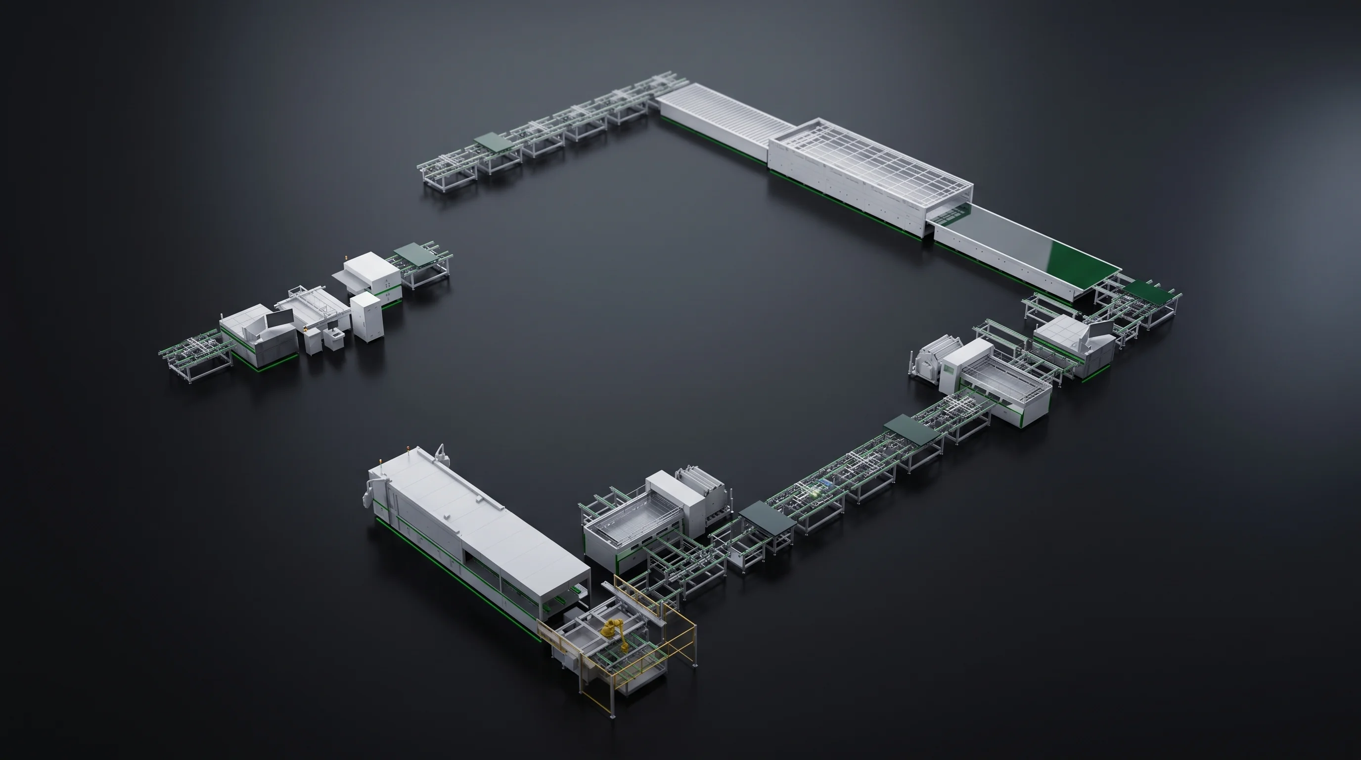
L-shaped module line laid out with both cell formats allowed for
Nominated early, the second format arrives with the machine.

What comes back

  • The machine list with both formats marked against each window
  • The tooling each format needs
  • The table rows that will differ between them
Test station set against the parameter table both formats are read on
Both formats against the same table.

Decided at order time

Three Limits Module Line Cell Compatibility Cannot Reach

Three things sit outside what a tooling change reaches, and all three are settled when the equipment list is written rather than afterwards.

We say so before the machine is specified, because none of the three can be bought back later.

01

Cell pitch below zero

It belongs to how the SML-S60 places and holds cells, so it comes with that machine rather than being fitted to another one later. Our BC route page sets out where that matters in an equipment list.

02

Aluminium back-surface cells

The SML-C20 suits monocrystalline and PERC cells inside its 156 to 220 mm window. Aluminium back-surface cells sit outside that window, so a plant running them scribes on a different basis.

03

Models outside these six

The six machines on this page carry technical agreements with parameter tables to be accepted against. Other models in our range are named and shown, and the figures they can be held to are written when their agreement is.

Test station configured for a module type outside the standard window
Outside the window is a different specification, not a tooling order.
Integrated cell whose parameter table is written at order time
Written when the agreement is.
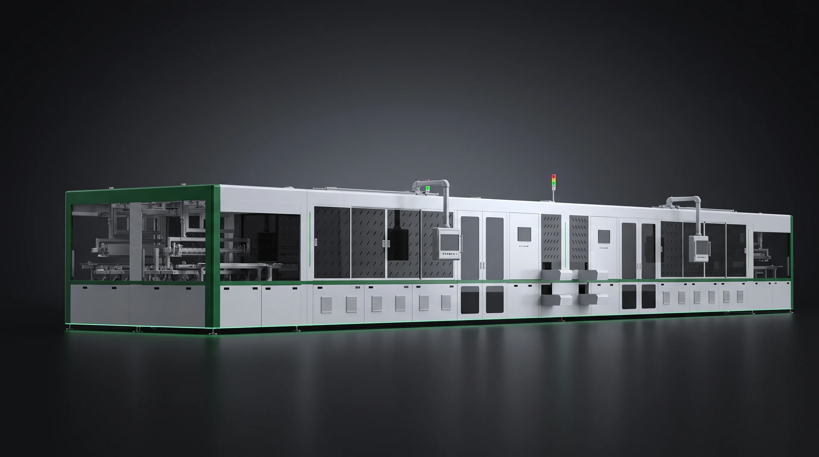
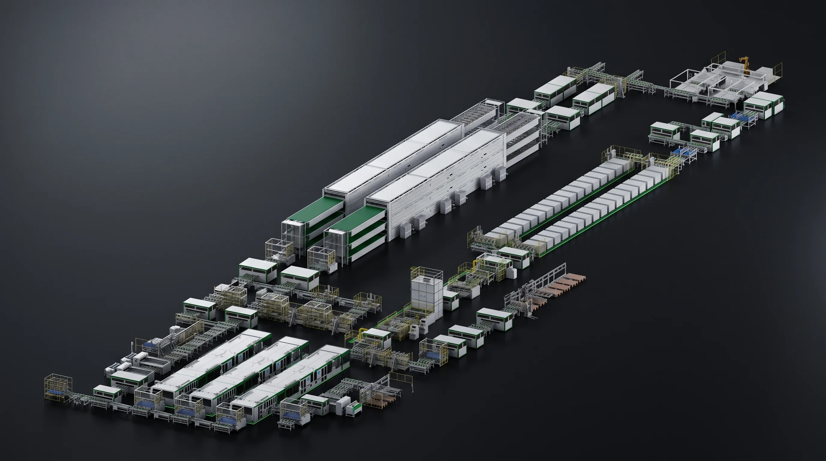
Complete module line in isometric view, module line cell compatibility settled before the build

Send your two cell drawings

Drawing, Busbar Count, Thickness, String Length

Send those four for the format you start on and the format you expect to add. The machine list, the window check and the tooling items for both come back within 24 hours.

What comes back
Both formats marked against every machine window
If the second format is open
Send both candidates and we mark what each one adds

How to reach you

[email protected]