
Multi-busbar stringer
SML-S40 Multi-Busbar Stringer — Two Throughput Gears, Set by Busbar Count
The multi-busbar stringer for TOPCon and PERC — the one machine here whose rated output is stated as two gears, so the number you plan against is the one your string actually runs.
3–12BB
≥3400
pcs/h · 182–210 mm half cell
13–20BB
≥3200
pcs/h · 182–210 mm half cell
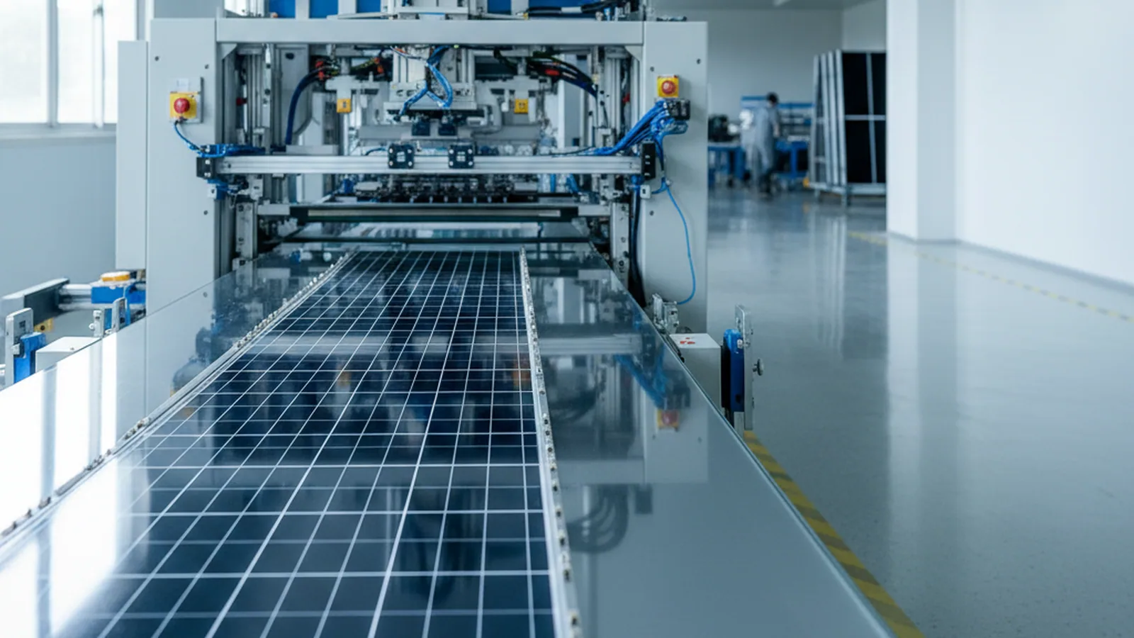
TOPCon & PERC half cells in → multi-busbar strings out
Where it sits
Where This Machine Sits
Fix the position before the parameters. On the TOPCon and PERC route this is the stringing station — cells arrive scribed into halves, finished strings leave to layup.
Positive Pitch Defines the In-Feed
What makes its interfaces specific is the pitch it runs. The SML-S40 lays cells at positive pitch, 1 to 5 mm apart, so the in-feed expects positive-pitch scribed half cells — not the near-touching layout of a BC line.
Settle the in-feed early
The machine expects cells already separated at scribing. If your upstream still snaps cells over an edge, the seam between the two stations is the place to watch — not the stringer itself. On the out-feed it hands strings to a layup machine or runs standalone, with the docking height supplied up front.
Who it's for
Who This Machine Is For
A route-specific stringer is not a universal one. This split isn't a ranking — it's which route and pitch each machine was built to hold, so you land on the right page the first time.
Built for this machine
- TOPCon and PERC cells, 166–210 mm — half cells on the positive-pitch route.
- Positive pitch, 1–5 mm — standard spacing for TOPCon and PERC layouts, laid to ±0.3 mm.
- Busbar counts that keep climbing — 3BB–20BB now, with 25BB-ready headroom for the next roadmap.
- Cells down to 110 μm — thin-cell capable, with the chipping boundary marked below.

Not this machine — where to go
- BC, negative-pitch stringing — the near-edge-to-edge BC layout runs on the SML-S60, built for negative pitch.
- Lower throughput or entry budget — the SML-S15 is the entry stringer on this same route.
Pitch is the line that separates these two stringers: the SML-S40 runs the positive-pitch TOPCon and PERC route, the SML-S60 runs the negative-pitch BC route, and neither is a cut-down of the other. To rank the three stringers by route, pitch and gear, see the tabber stringer machine page →
Full spec
Full Specification
Read this table by your own busbar count first — the two throughput rows are the ones most likely to be misread, so take the row that matches the string you run, not the higher figure.
3–12BB holds ≥3400 pcs/h, 13–20BB holds ≥3200 pcs/h. Everything that follows explains the numbers; this one is the checklist your process team reads against the drawing on your desk.
| Parameter | Value |
|---|---|
| Cell | |
| Applicable cell | PERC / TOPCon, 166–210 mm, half cell |
| Busbar count | 3BB–20BB, 25BB-ready |
| Cell thickness | 110–200 μm |
| Throughput | |
| Capacity, 3–12BB | ≥3400 pcs/h (182–210 mm half cell) |
| Capacity, 13–20BB | ≥3200 pcs/h (182–210 mm half cell) |
| Utilization | ≥95% |
| Chipping rate | ≤0.25% (A-grade)Holds at ≥110 μm; rises on ultra-thin cells. |
| Precision | |
| Positioning accuracy | ≤±0.1 mm; angle ≤±0.04° |
| Cell pitch | positive 1–5 mm |
| String length | ≤1400 mm |
| Welding | |
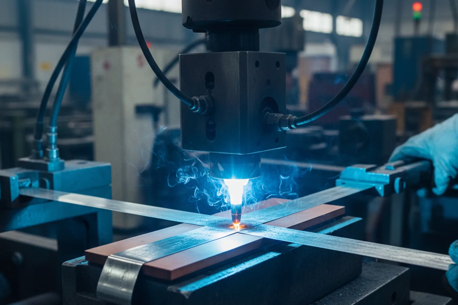
| Method | infrared; flux by ribbon dip; ribbon flattened before weld |
| Weld pull force, front | ≥0.5 N (0.4 mm ribbon) |
| Weld pull force, back | ≥1 N (0.4 mm ribbon) |
| Ribbon flattening | 0.29 mm round → 0.12–0.15 mm thick, 4.8–6 mm long |
| Feeding | |
| Magazine | 5 groups (1 working + 2 waiting + 2 empty); 300 small cells |
| Power & utilities | |
| Power | avg 40 kW, peak 60 kW |
| Air | ≥1200 L/min; two φ16 mm hoses in parallel |
| Exhaust | top φ102 mm; >600 m³/h |
| Footprint | |
| Dimensions | 7850×1600×2500 mm (front 5750 / rear 2100) |
| Weight | 4500 kg |

Infrared welding station

Five-group magazine
Two-face weld
Why the Two Faces Are Welded to Different Numbers
A single ribbon is soldered to both faces of the cell in the same pass, and the two joints are held to different pull-force floors — front ≥0.5 N, back ≥1 N, both on 0.4 mm ribbon.
One Threshold Would Test the Wrong Joint
Not a typo, and not a stronger machine on one side; the two faces are simply different bonding conditions. Get them mixed up and you test the wrong joint.
Check both to the front number and a weak back joint passes; demand the back number everywhere and you fail good front joints, slowing the line to chase a threshold the front was never meant to meet.
Different Faces, Different Bonding Conditions
The reason the faces differ is the surface each joint forms against. The front and back of a TOPCon or PERC cell present different metallization and a different pad, so the same ribbon, the same flux and the same infrared profile produce two bonds that don't carry load identically. Rather than pretend one number covers both, the machine is qualified with a floor per face — the value each bond can actually hold.
Two Floors, Read Separately
So the pull-force check on this stringer is read as two lines, not one. Each is a floor, not an average — a string that meets ≥0.5 N on the front and ≥1 N on the back is sound on both faces, which is the only way a two-face weld is actually sound.
Set acceptance sampling to pull both faces, then. A batch that only tests the front leaves the ≥1 N back joint unverified — and the back is the harder of the two to make well.

Ribbon prep
How the Ribbon Is Prepared and Laid
A joint is only as good as the ribbon that enters it, so the machine conditions the ribbon in three moves before the weld is asked to hold anything. Run them out of order and the weld inherits a ribbon that never had a chance.
Flux by ribbon dip
The ribbon is fluxed by immersion, so it carries flux into every joint evenly — not by a spray that can run dry across a wide multi-busbar cell.
Infrared welding
The fluxed ribbon is brought onto the pads and the joint forms under infrared heat, front and back in the one pass.
Ribbon flattened before it welds
A 0.29 mm round ribbon is pressed to 0.12–0.15 mm thick and 4.8–6 mm long at each pad, so a wide, flat contact meets the busbar instead of the thin line a round wire would touch.
Flattening is the step that pays back at high busbar counts. More busbars means more joints per cell, and a round ribbon touching each pad on a narrow line leaves less bonded area to carry current and load.
Pressing the ribbon flat first turns each of those contacts into a broad footprint — before the infrared pass ever runs.
Flux dip
Flattened ribbon
The numbers
The Three Numbers Behind the String
These are the numbers your rated line is signed against — the throughput gear, the placement, and the breakage floor. No reading required; glance and you know the class.
≥3400 / ≥3200
pcs/h — throughput, 3–12BB and 13–20BB
≤±0.1 mm
Positioning accuracy · angle ≤±0.04°
≤0.25%
Chipping rate, A-grade cells
The two throughput figures are the gears from the top of the page, restated as the signed floor: whichever busbar count you run, that is the rate the acceptance table holds the machine to. Chipping rate holds at ≥110 μm and rises on ultra-thin cells, so it is read against your own thickness.
Placement
How Placement Lands the Ribbon on the Pad
Placement here has one job the two-face weld depends on: put every cell where the flattened ribbon lands centered on its busbar pads. Positioning holds ≤±0.1 mm with angle ≤±0.04° — the tolerance the whole weld argument rests on.
- 1
Offset holds the footprint on the pad
A cell set even slightly askew moves the pad out from under the flat ribbon footprint, and a footprint that lands half on the pad is a joint that meets neither the front nor the back floor. Holding ≤±0.1 mm is what keeps the contact where it counts.
- 2
Flatten and place are two halves of one result
The ribbon is pressed to a 0.12–0.15 mm footprint so it has area to bond; placement keeps that footprint over the pad. Widen the ribbon but let the cell drift — or place perfectly under a ribbon that never flattened — and either way the joint gives up the contact the pull-force floors assume.
- 3
Angle carries the outer busbars
Across a multi-busbar cell, a small rotation throws the outermost pads furthest off their ribbon. The ≤±0.04° angle limit is what keeps the busbars at the edges landing as true as the ones in the middle, string after string.

One pitch, by design
One Pitch, by Design
One boundary is worth settling before the machine lands, because it's a route decision, not a shortfall you tune out later. The SML-S40 lays positive pitch, 1 to 5 mm — and only positive pitch — holding that spacing to ±0.3 mm.
That is the geometry TOPCon and PERC layouts are drawn on, and it is exactly what this machine is engineered to place accurately, cell after cell. So the one thing to read off your module drawing first is the cell-to-cell spacing — it decides more here than rate or budget do.
Cells sit with a gap — this machine
- Positive pitch, 1–5 mm — a gap between cells, held to ±0.3 mm across the string.
- If that's your layout, the S40 is built for it — this is the machine.
Cells overlap edge to edge — the S60
- A negative-pitch BC design is the wrong machine outright, not a setting you dial in.
- That geometry belongs to the SML-S60 — a positive-pitch stringer can't lay a module drawn to overlap.
Planning a route or format change is a separate subject with its own page. See the cell compatibility and changeover page →
Kept fed
Kept Fed by a Five-Group Magazine
A stringer only earns its gear if it doesn't stall to reload — on a line rated by capacity, a feed that runs dry quietly eats the number you signed for.
-
Five magazine groups
One working, two waiting and two empty, so a spent group is refilled off-line while the machine keeps drawing from the next.
-
300 small cells staged
Enough buffered ahead of the station that reloading doesn't break the takt of the running gear.
-
Refill without a takt stop
Because a group is always waiting behind the working one, the operator swaps at their own pace instead of against the line.
Your floor
Measure Your Floor First
This stringer draws the heaviest power of the three — plan for that before the crate ships. Below is the SML-S40's own row: footprint, weight and the 40 kW it pulls.
| Item | SML-S40 |
|---|---|
| Footprint | 7850×1600×2500 mm |
| Weight | 4500 kg |
| Power | avg 40 kW, peak 60 kW |
Other stringers
Not TOPCon/PERC? The Other Stringers
The two machines you'd move to from the SML-S40 sit in opposite directions. One stays on your route and steps the rate down; the other changes the route entirely and adds a pitch gear this machine doesn't have. Knowing which move you're making tells you which card to open.

SML-S60 — cross to BC, gain negative pitch
Leaves the positive-pitch route for BC and adds the negative-pitch overlap layout the S40 can't lay. The move when the cell itself is BC.
Compare
SML-S15 — same route, one gear down
Same TOPCon/PERC positive pitch as the S40, dropping from ≥3400 / ≥3200 to 1100 pcs/h — the move when the line is smaller or the budget is, not when the cell changes.
CompareAll three stringers set out by route, pitch and throughput gear on one page — see the tabber stringer machine page →
After you buy
After You Buy
One weld, two acceptance numbers — the easiest line on the table to read as a single figure.
Two faces, two pull-force floors
The SML-S40 is signed off on a front pull force ≥0.5 N and a back pull force ≥1 N, both on 0.4 mm ribbon; the back is held to twice the front because a back-side joint that clears the front floor can still be weak. Carry one number over from another stringer and you accept the back too loosely — write both into the agreement, and each face is tested against the floor meant for it.
See how acceptance is run
Get a proposal
Get Your Configuration Proposal
One drawing in, one proposal back — the low-commitment way to start, before anything is signed.
Both throughput gears sized to your route within 24 hours · email.