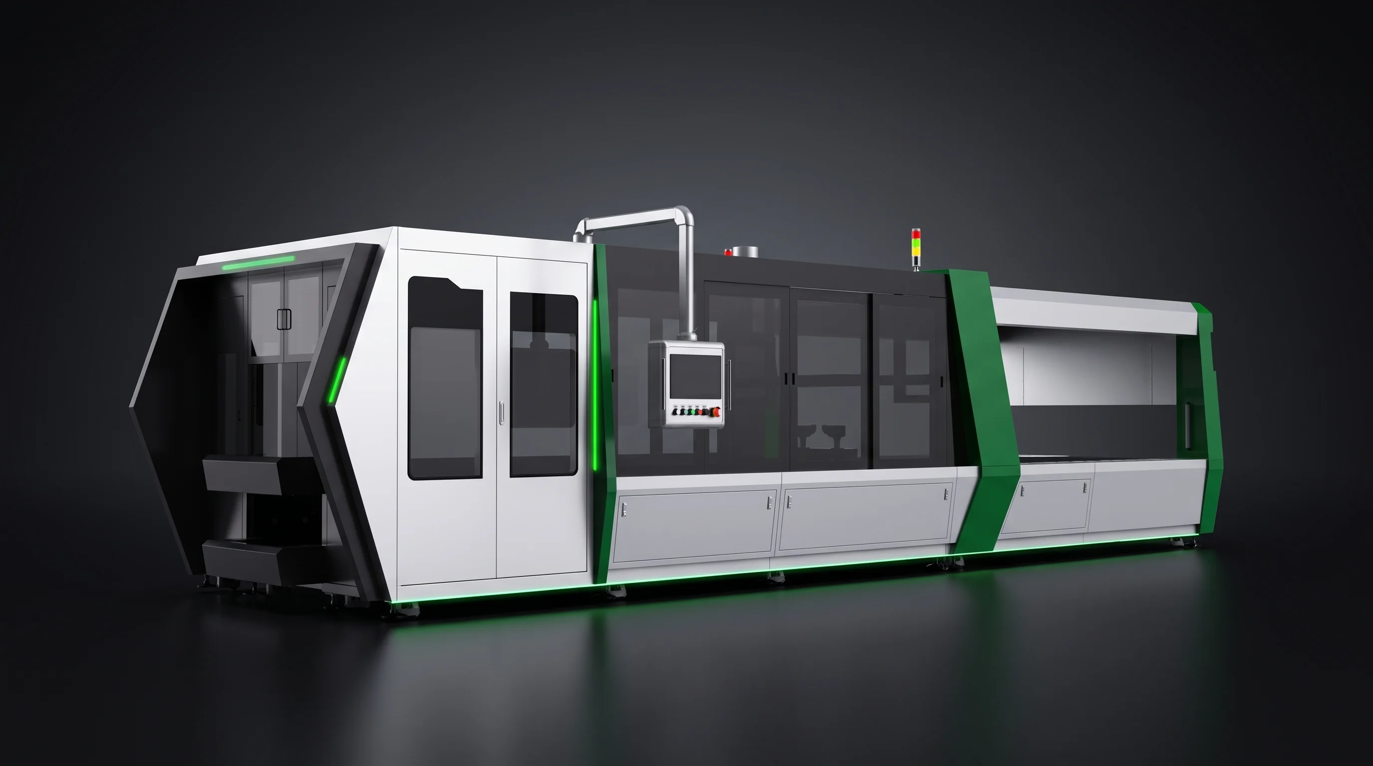
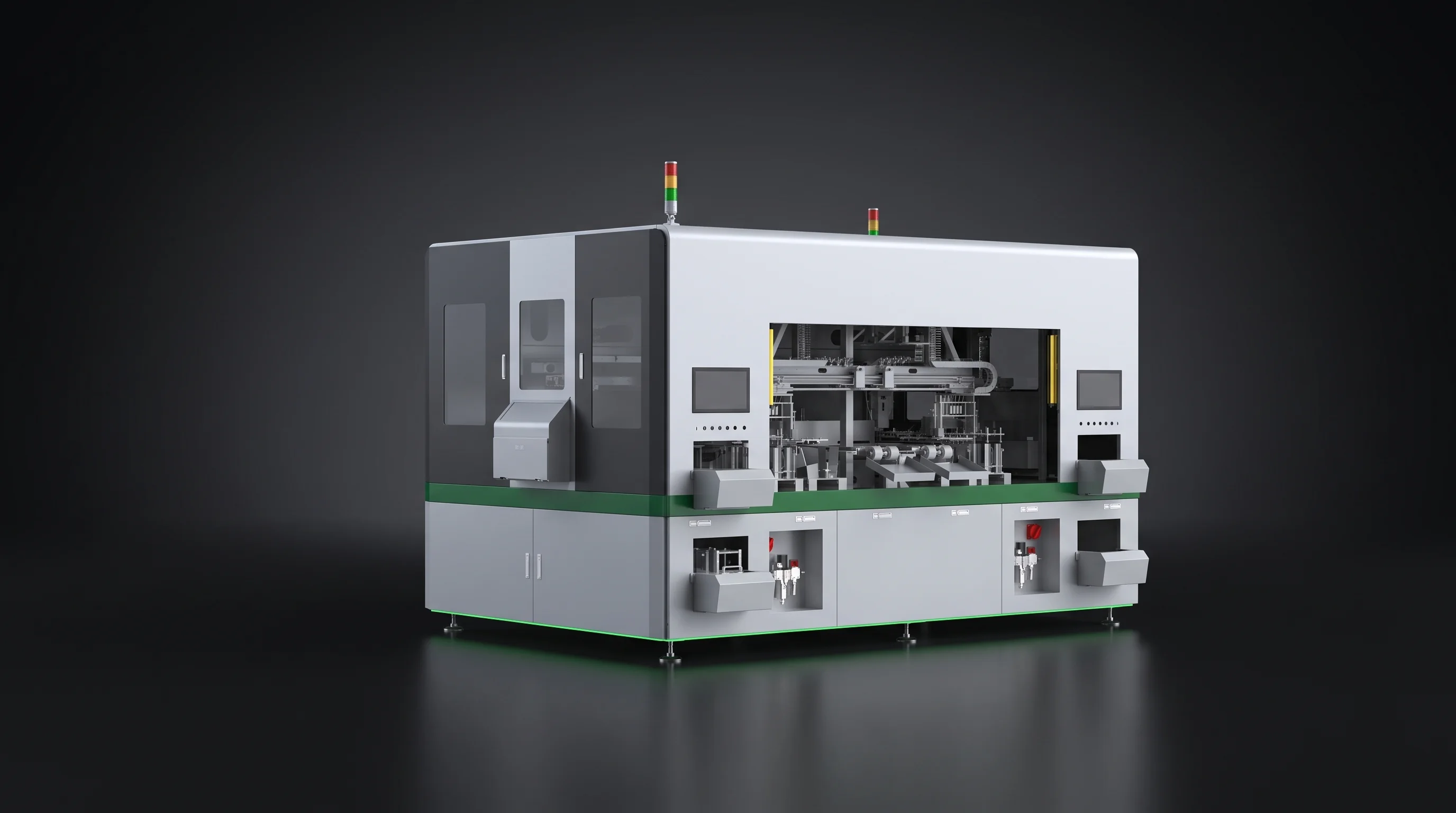
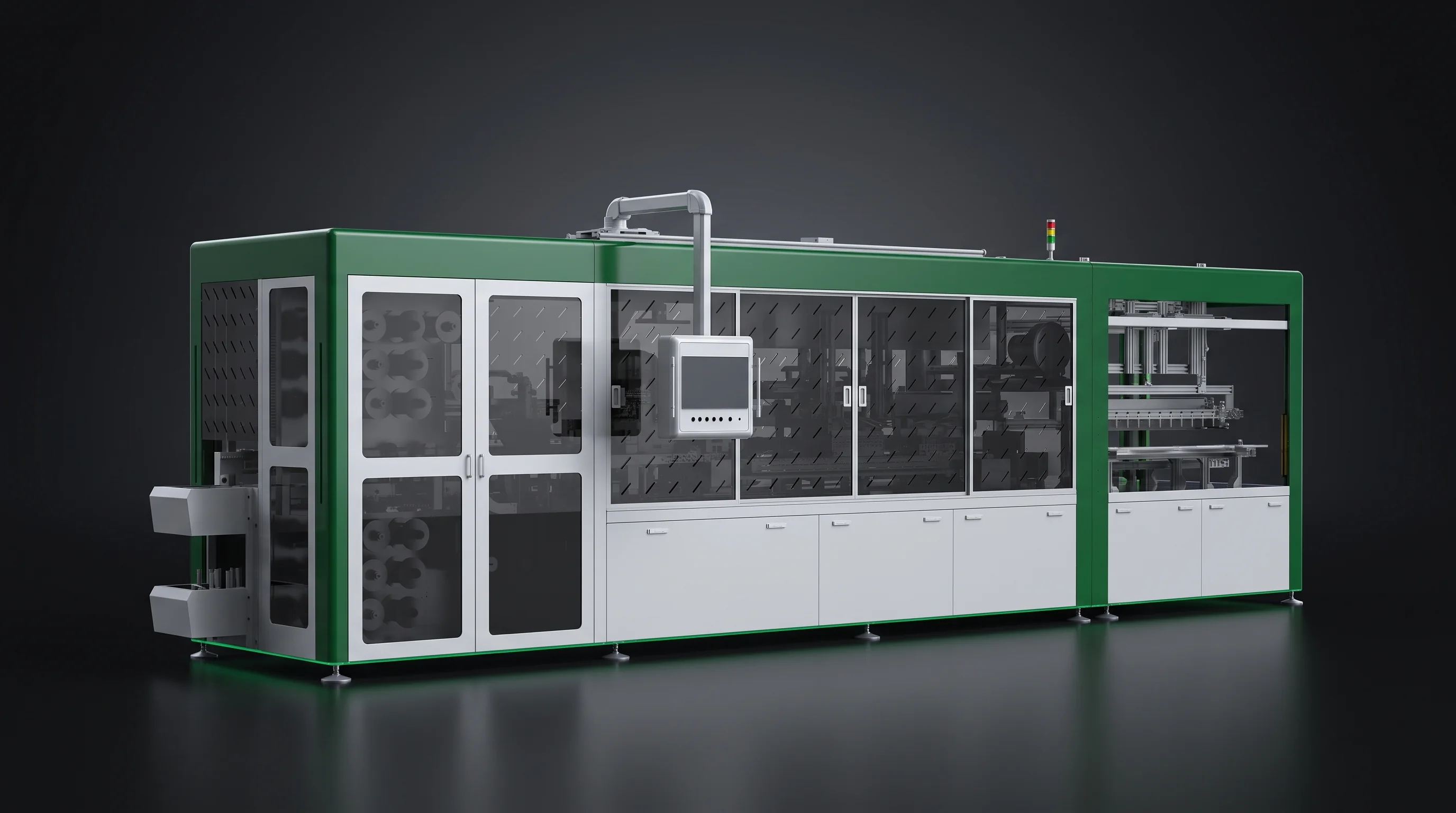
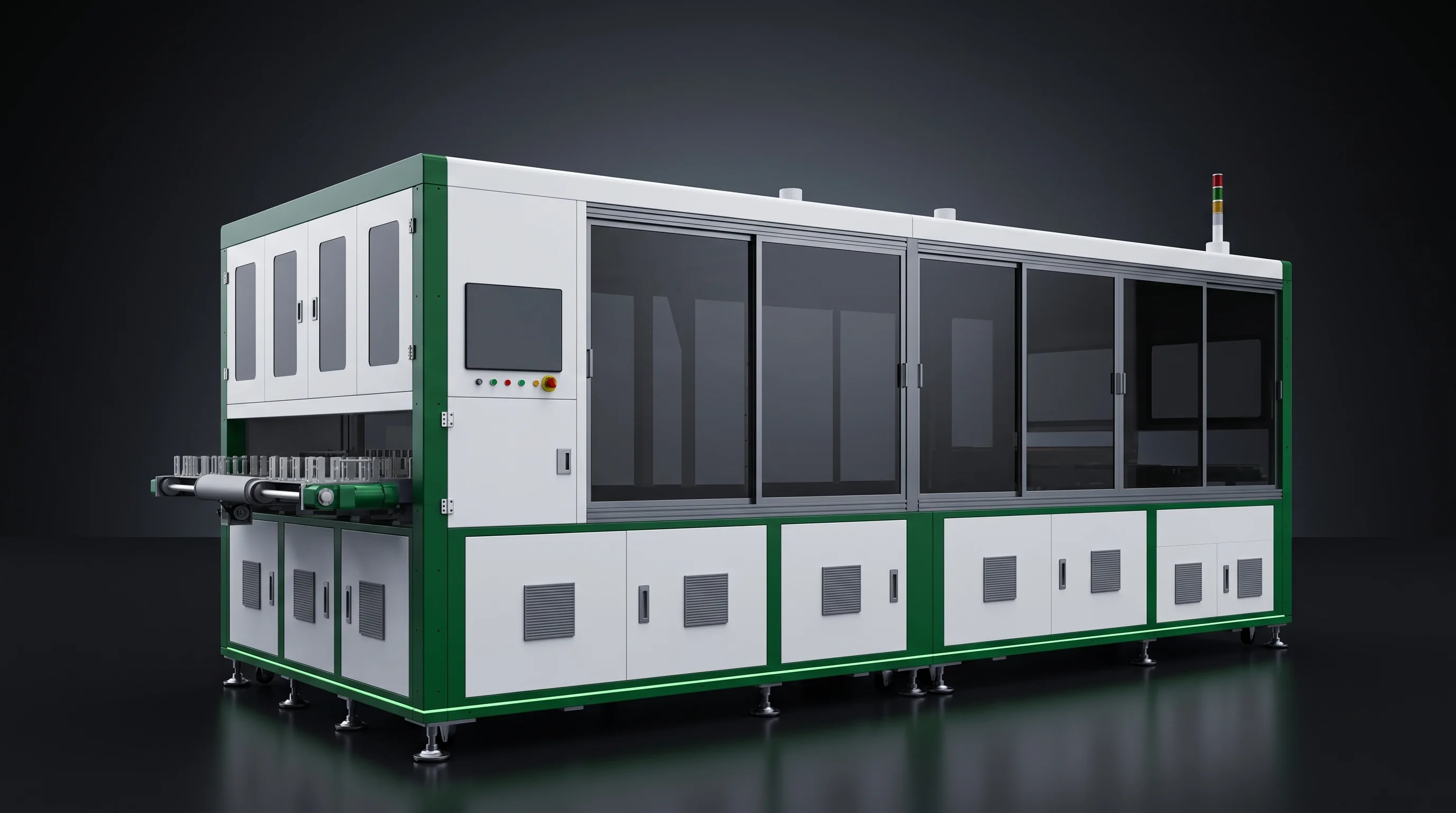
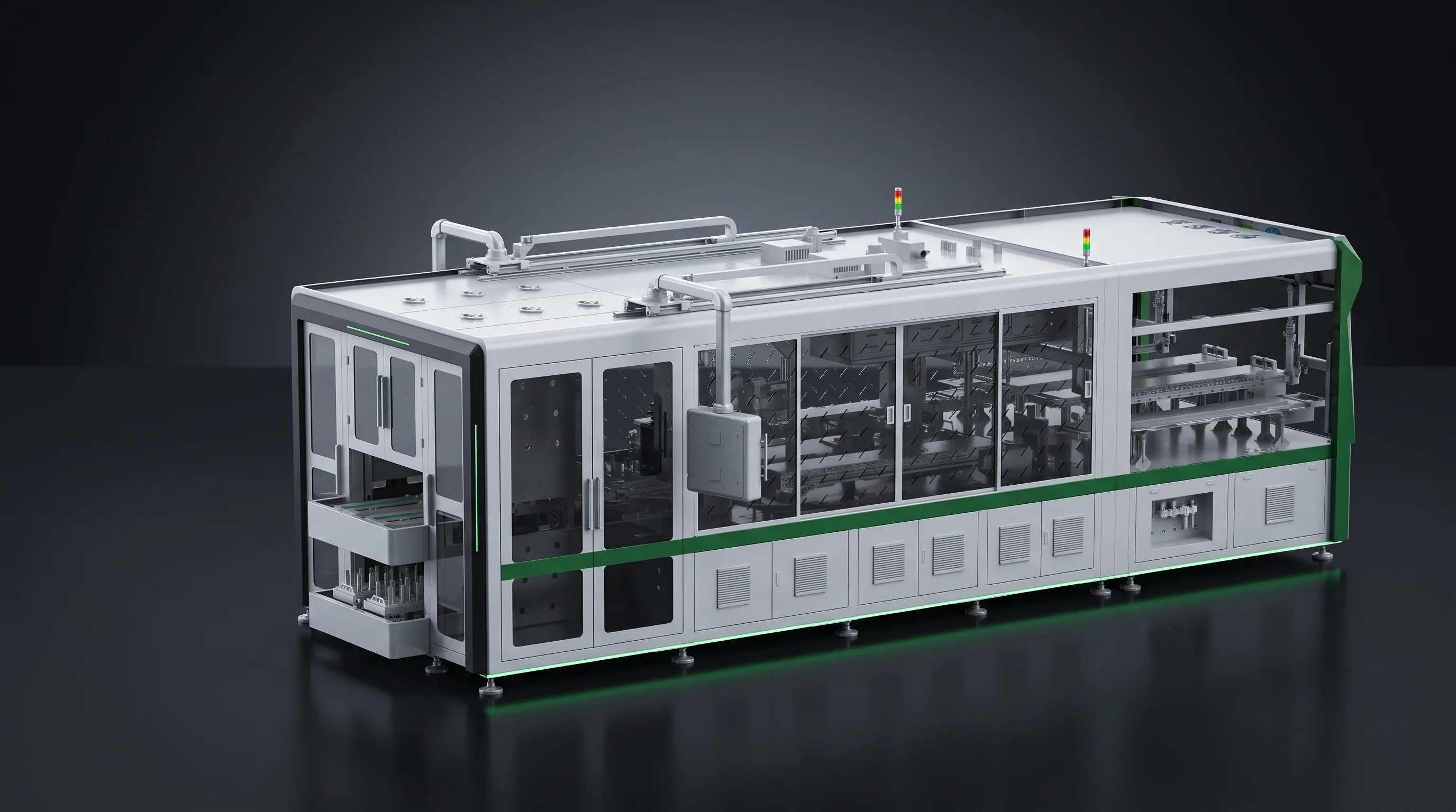
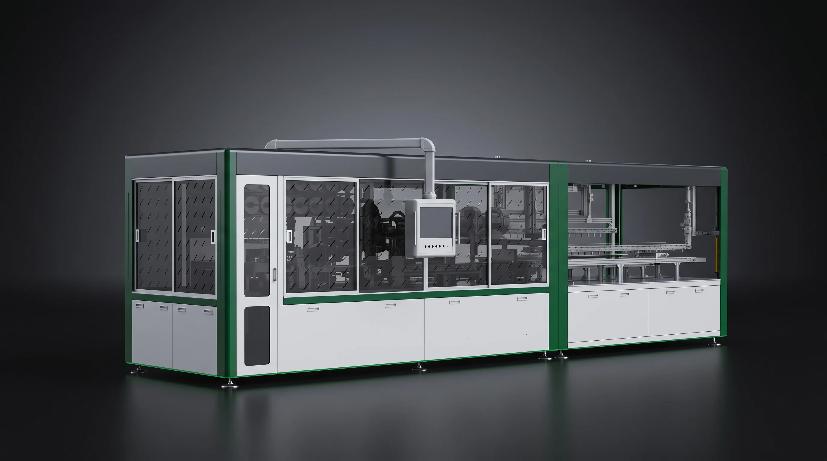
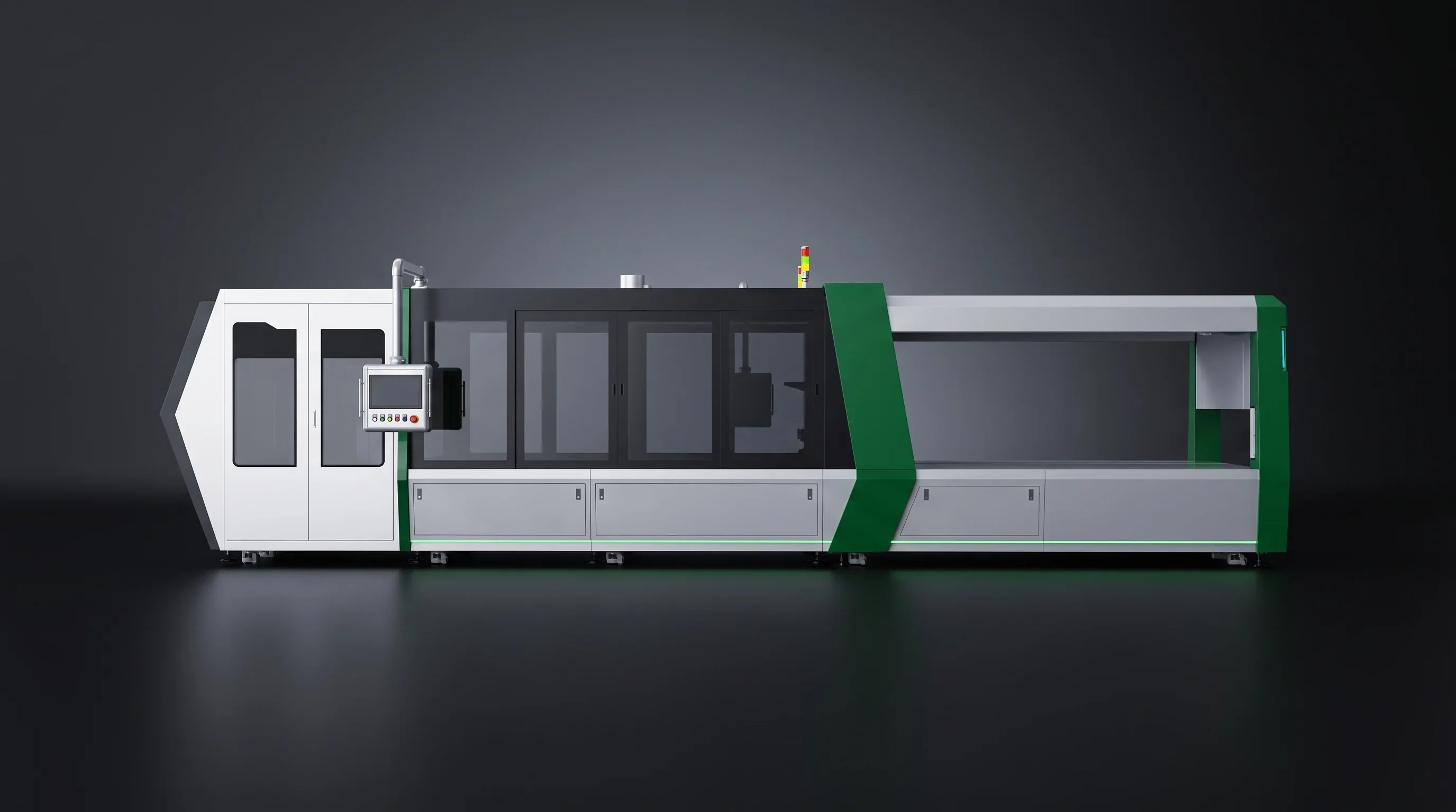
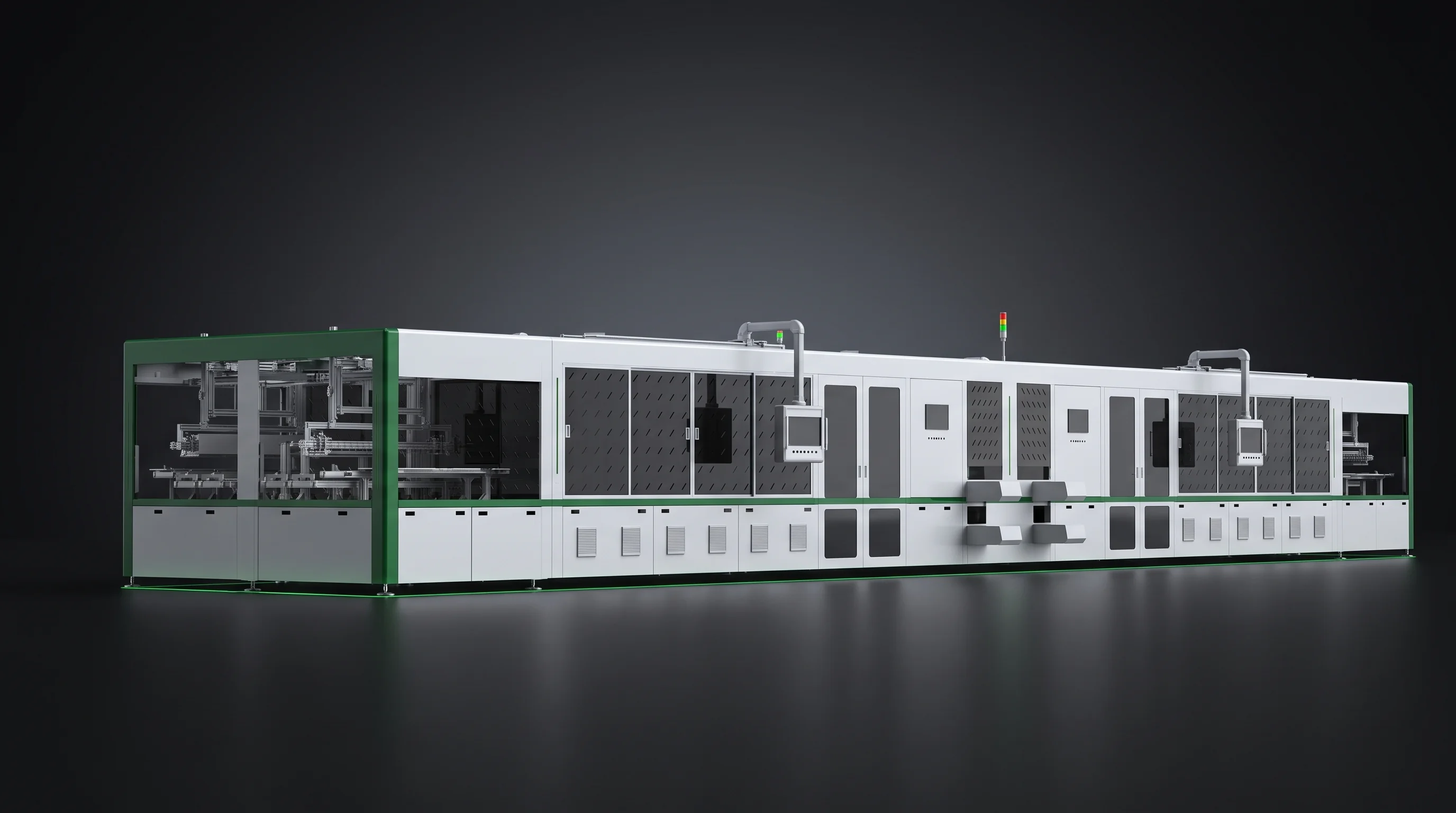
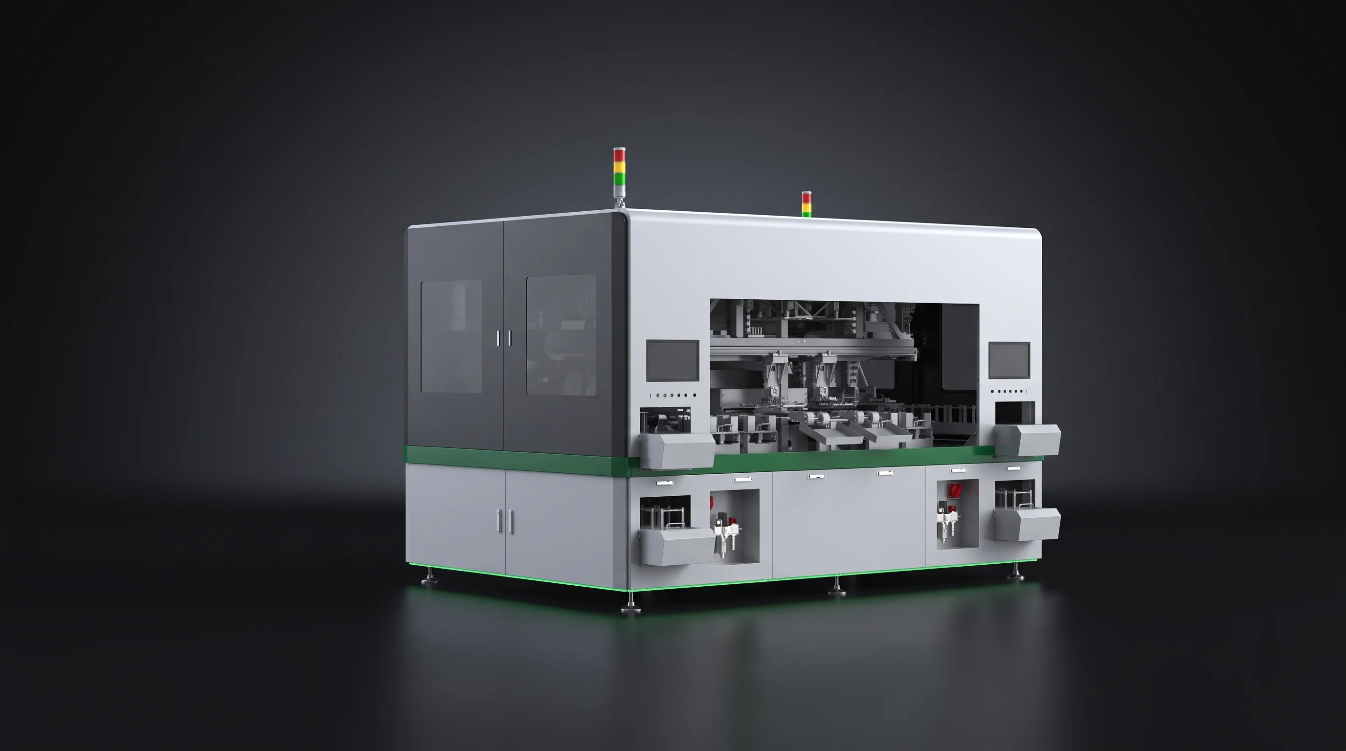
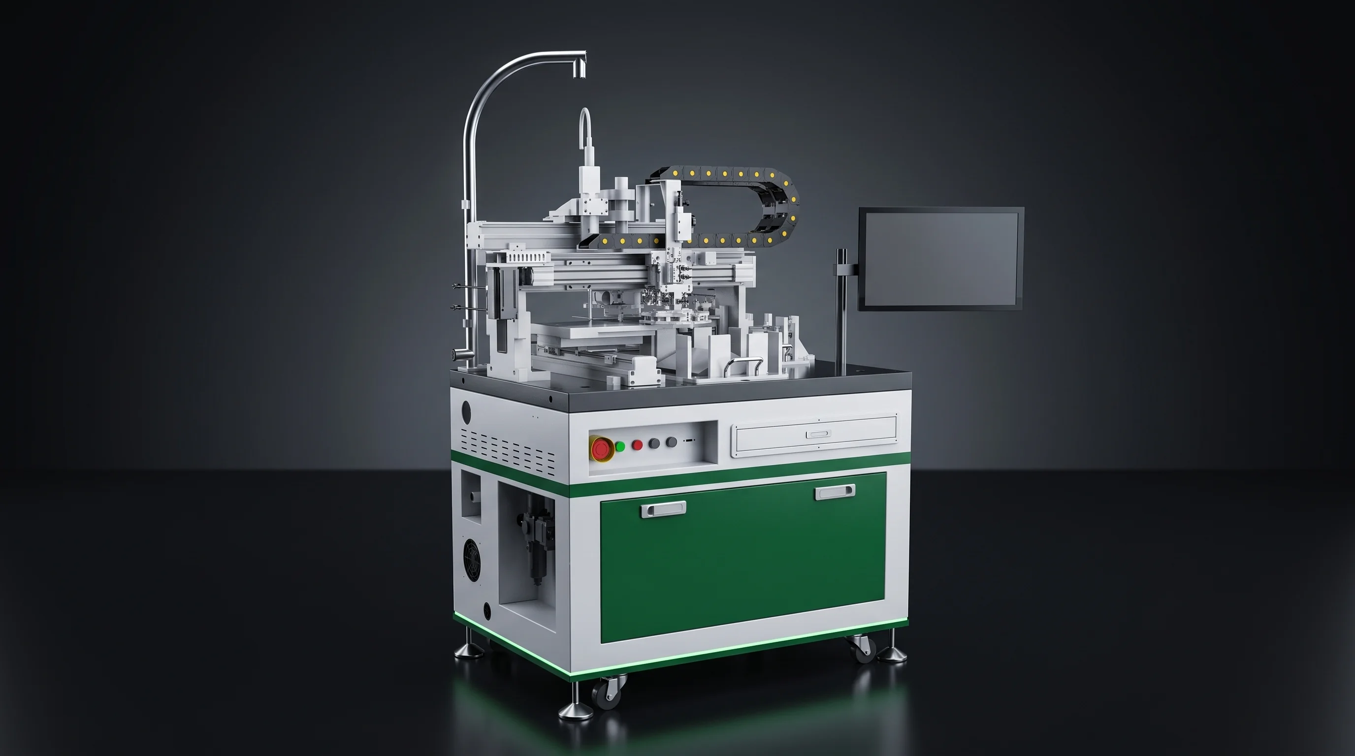
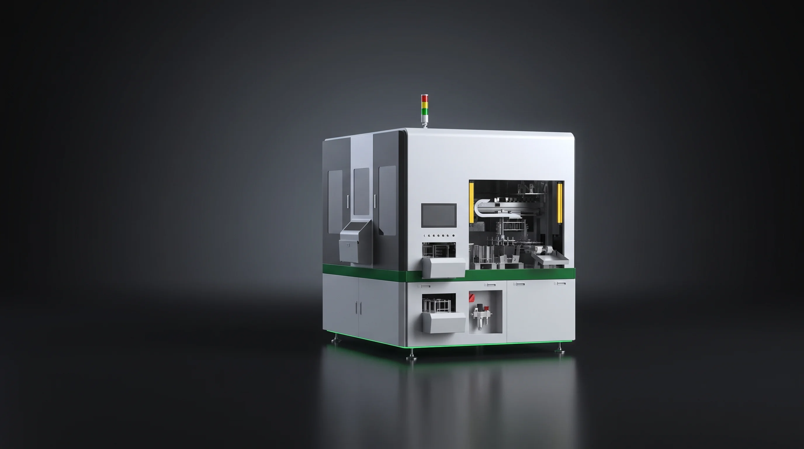
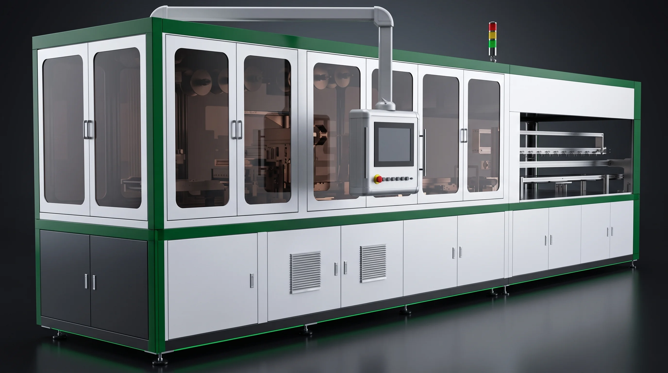
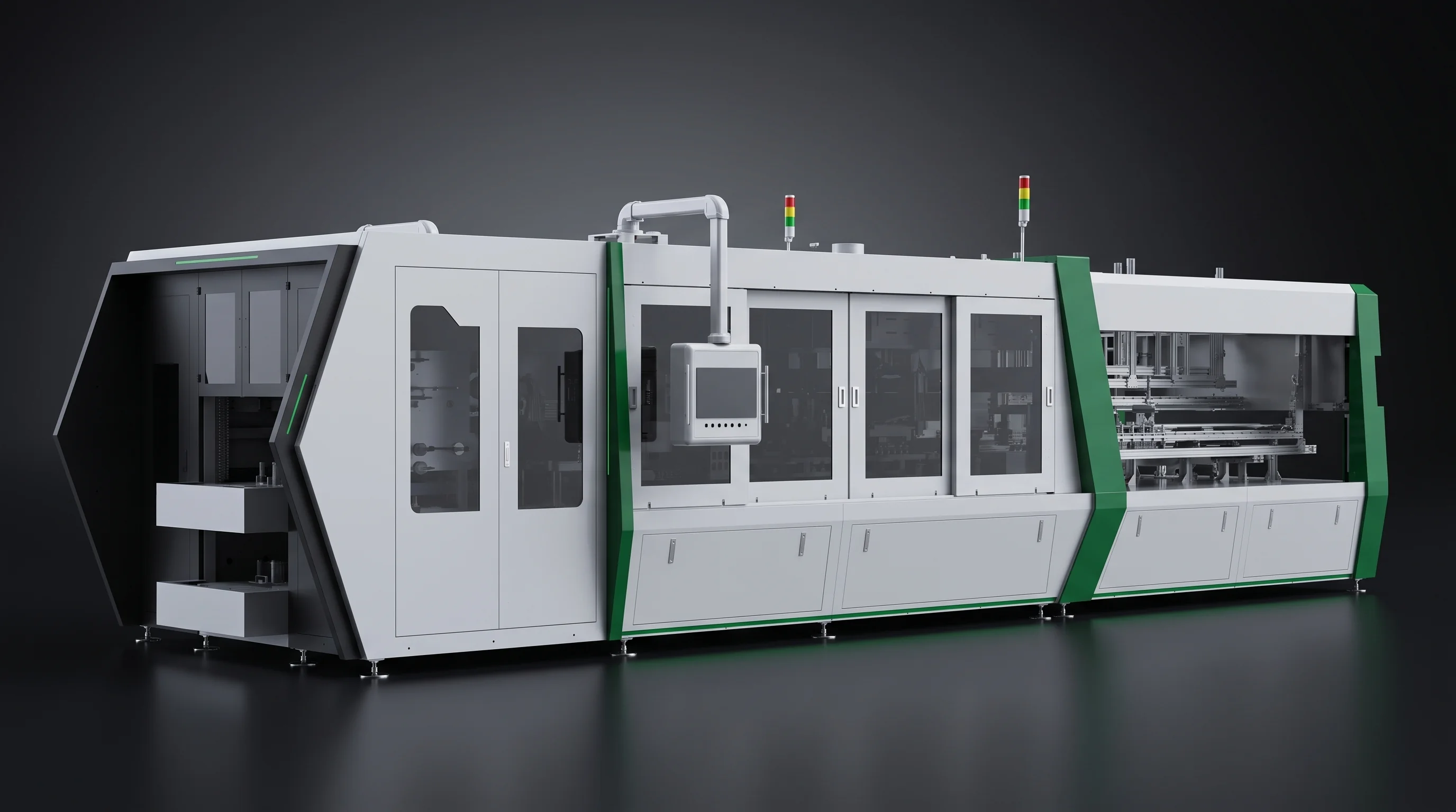
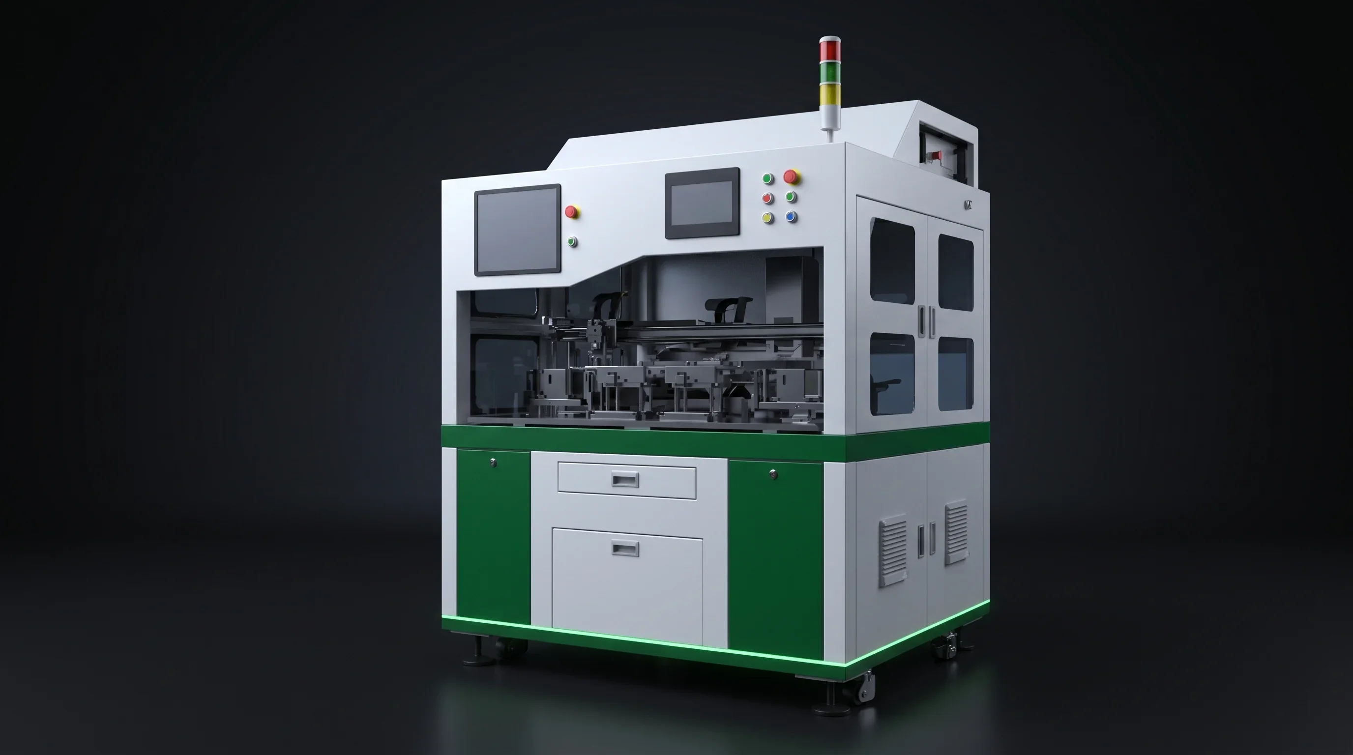
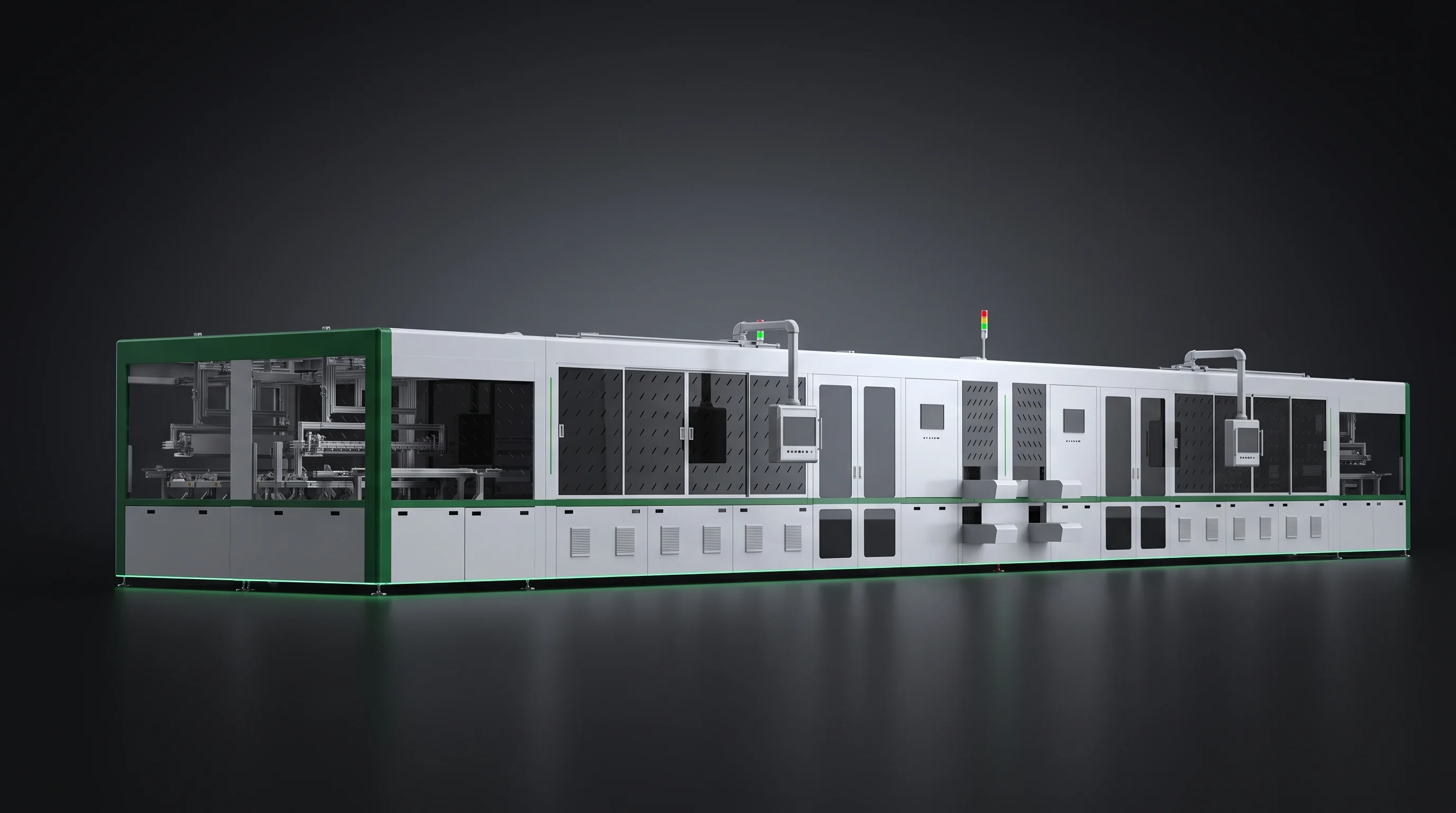
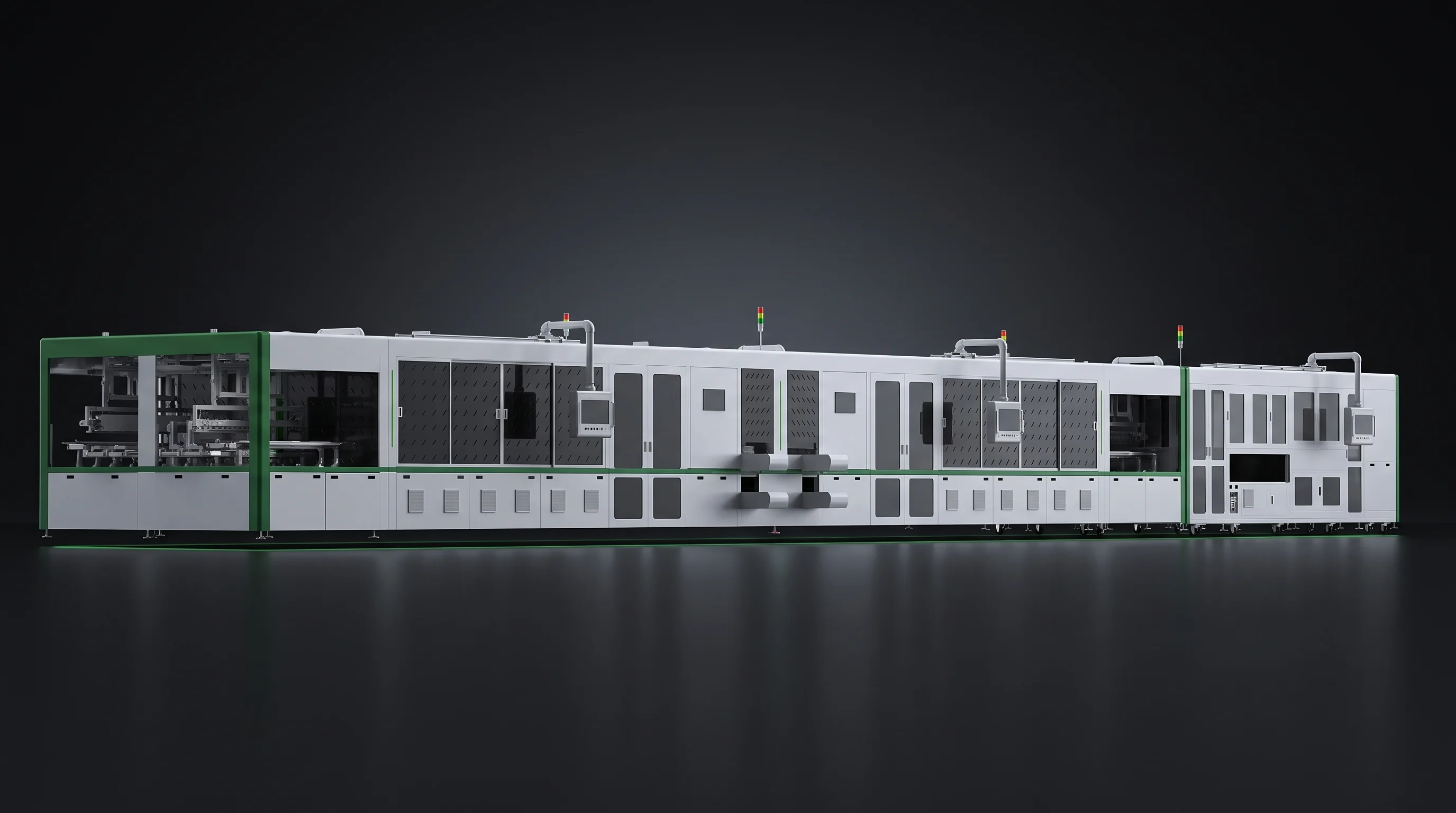
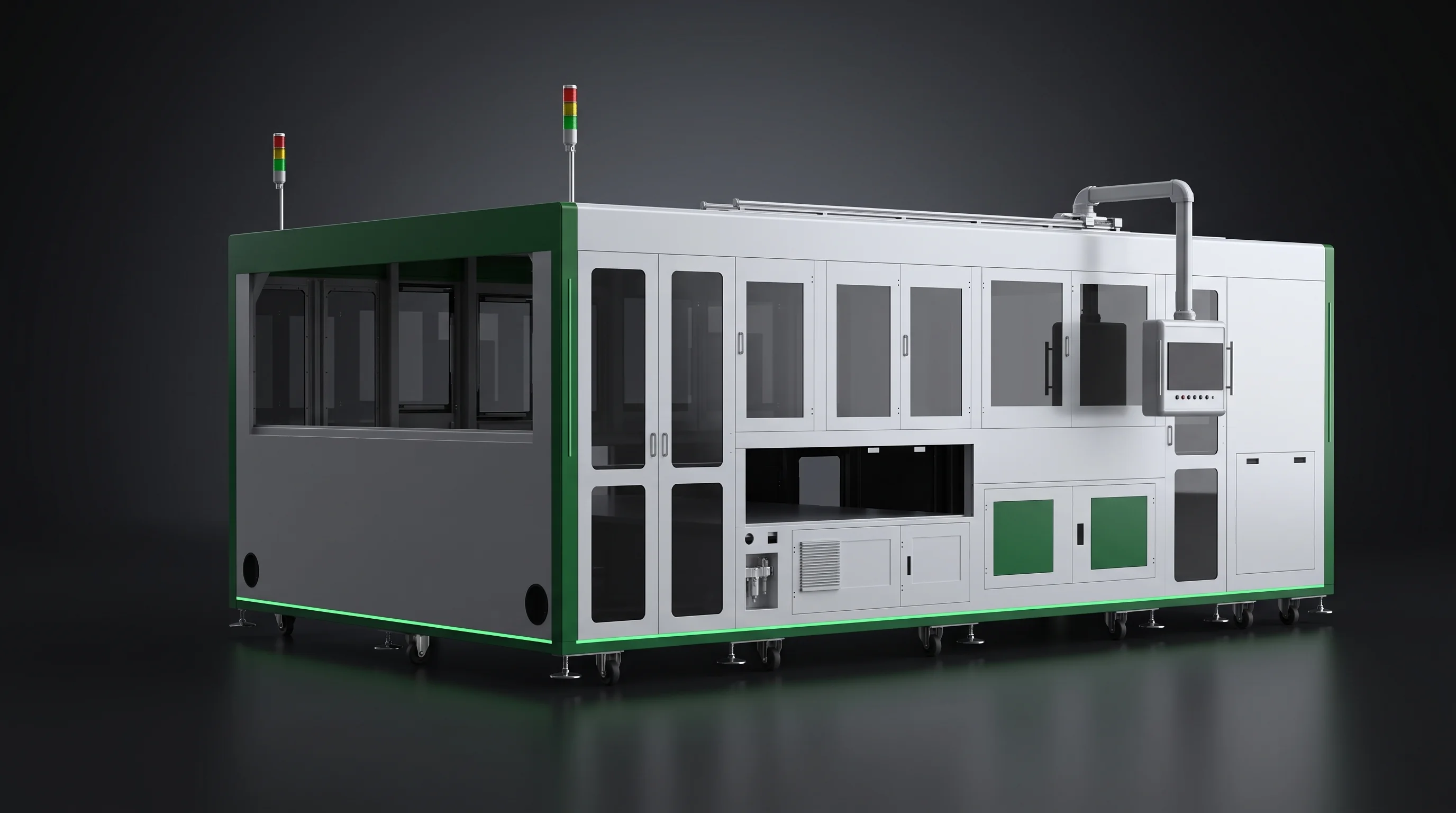
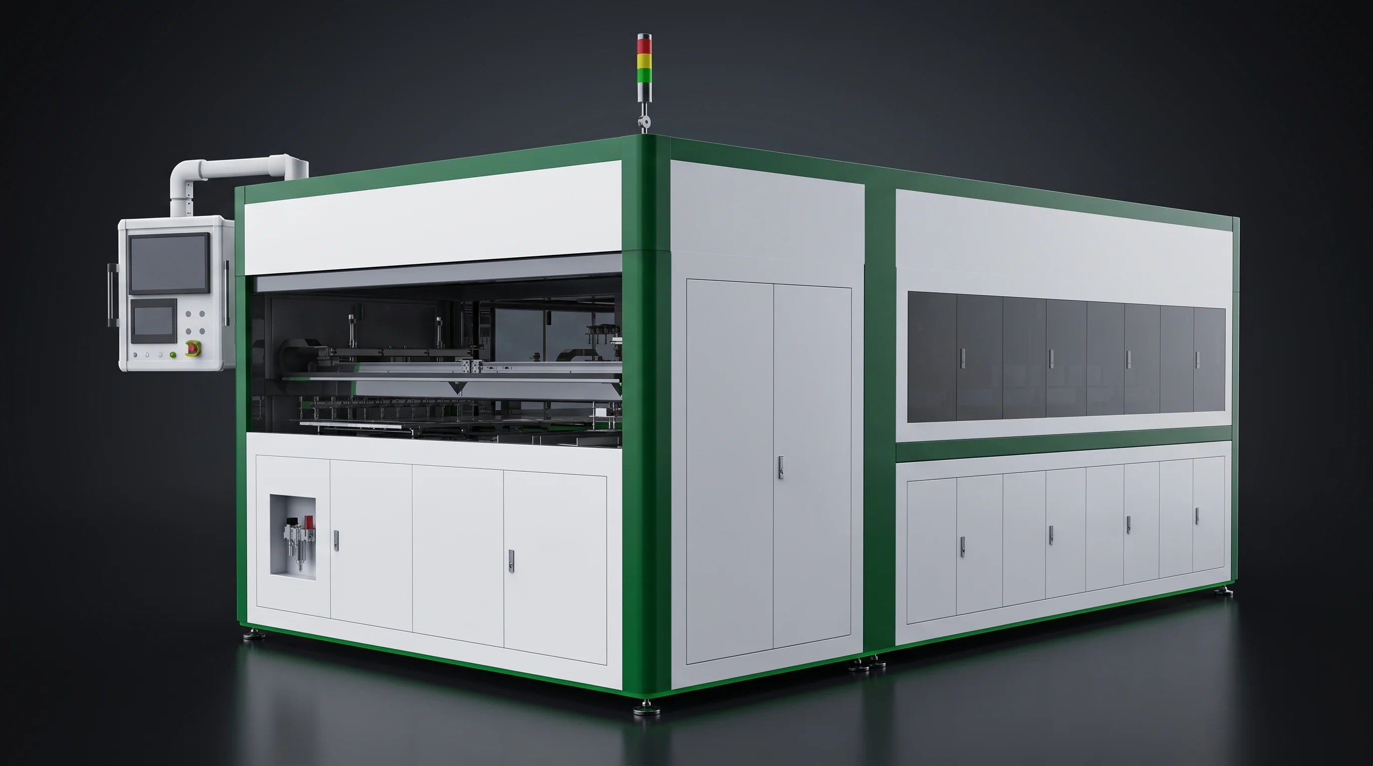
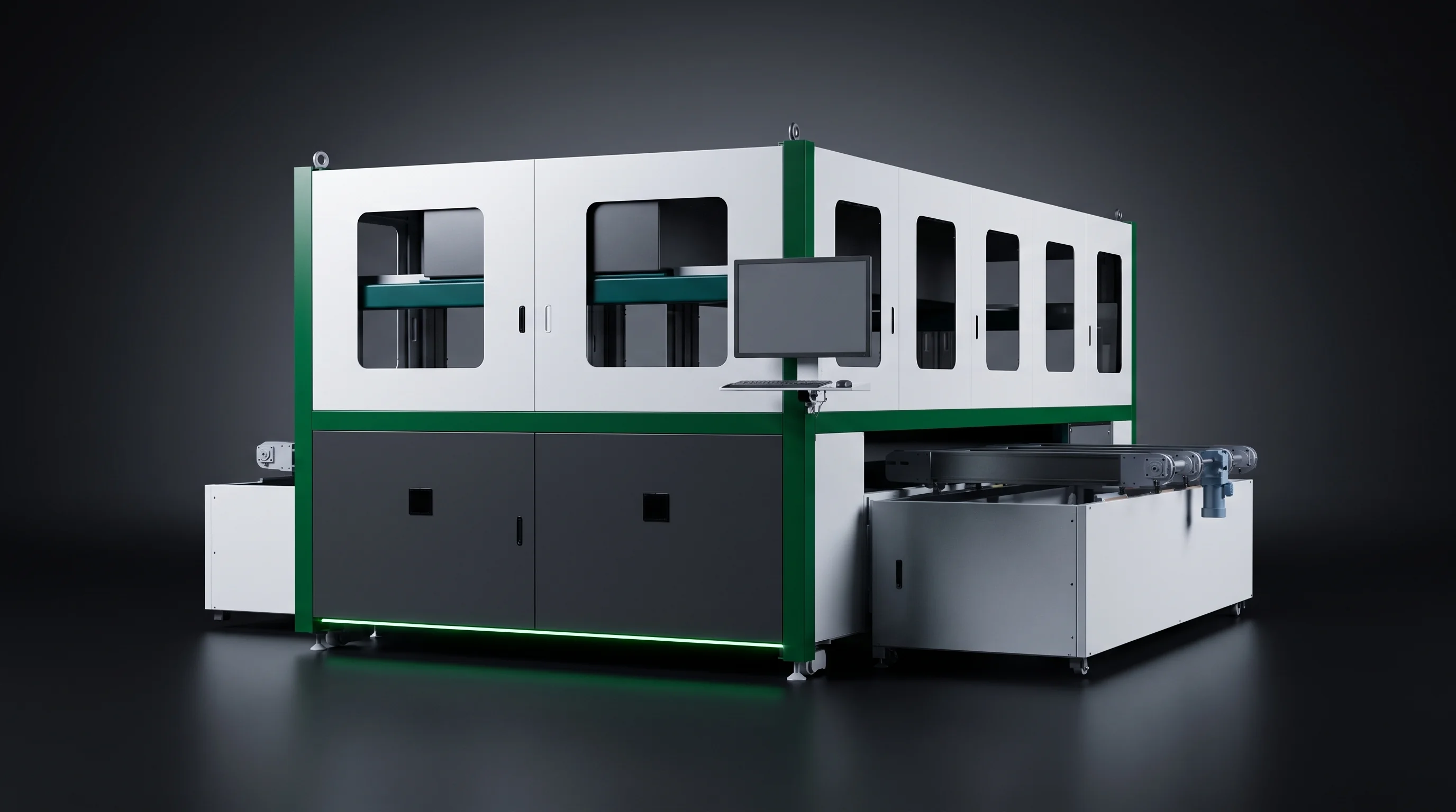
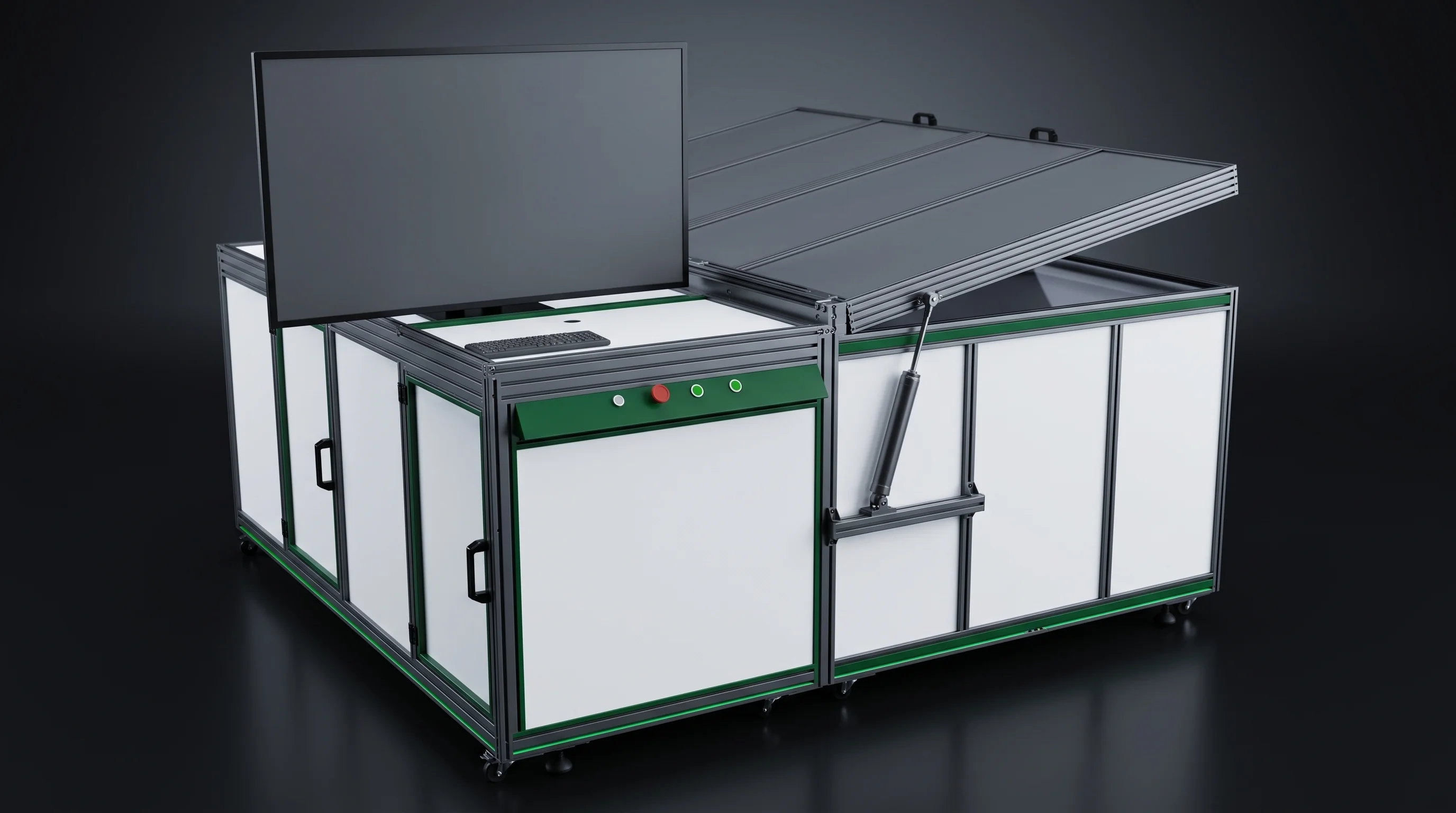
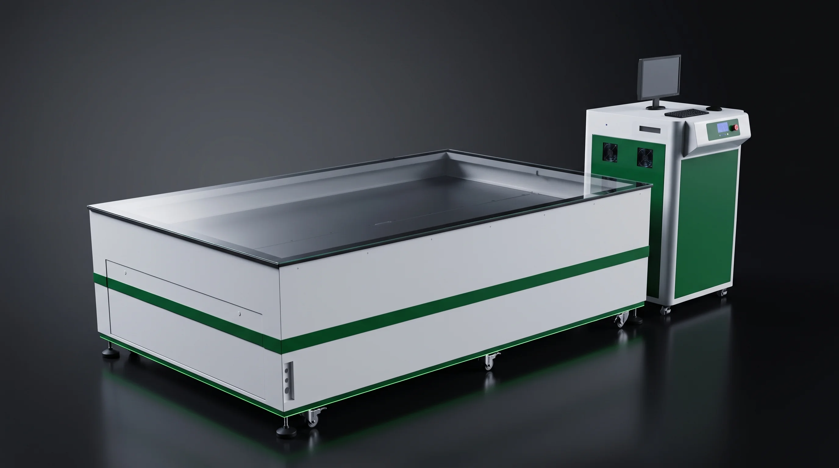
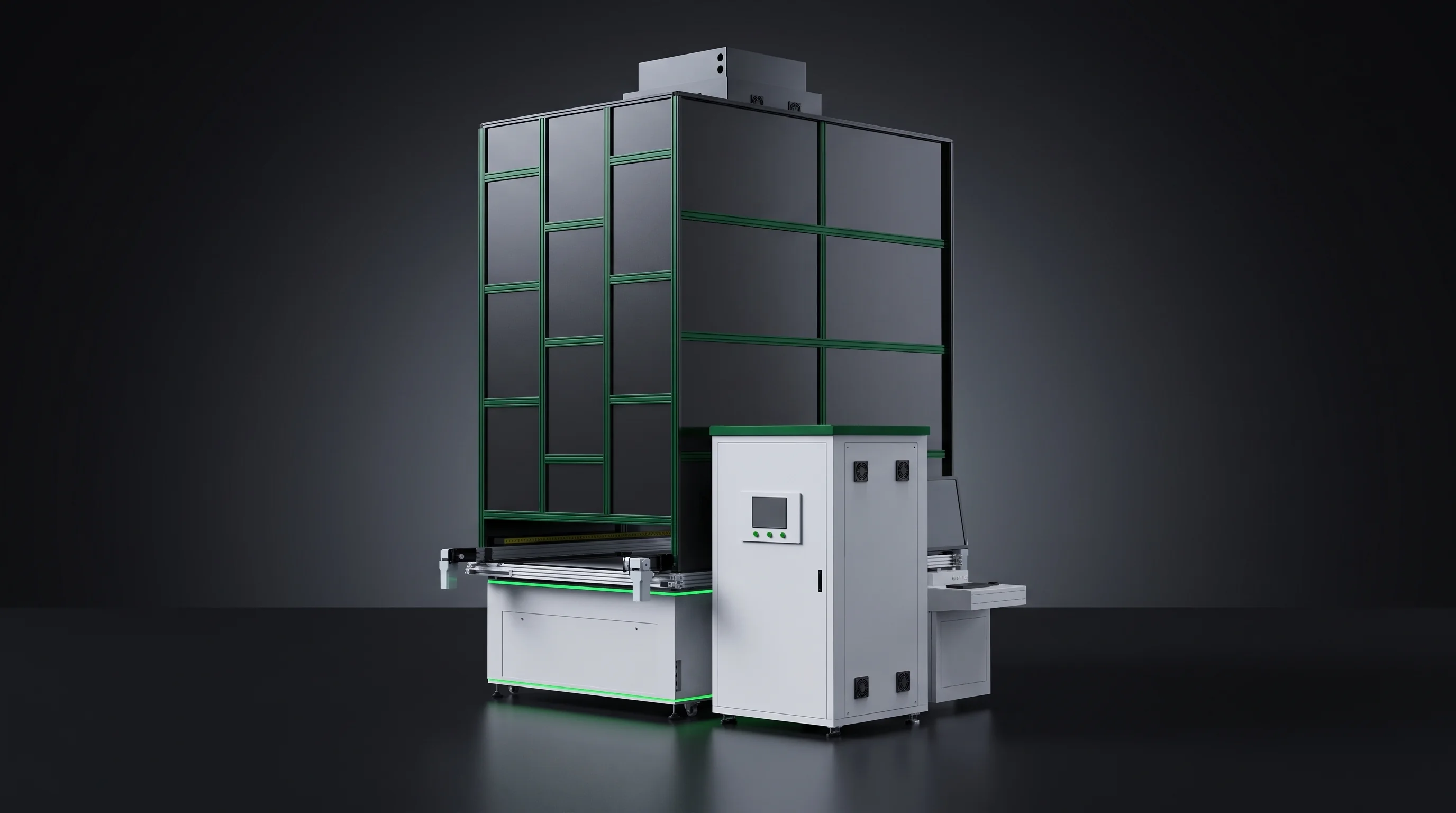
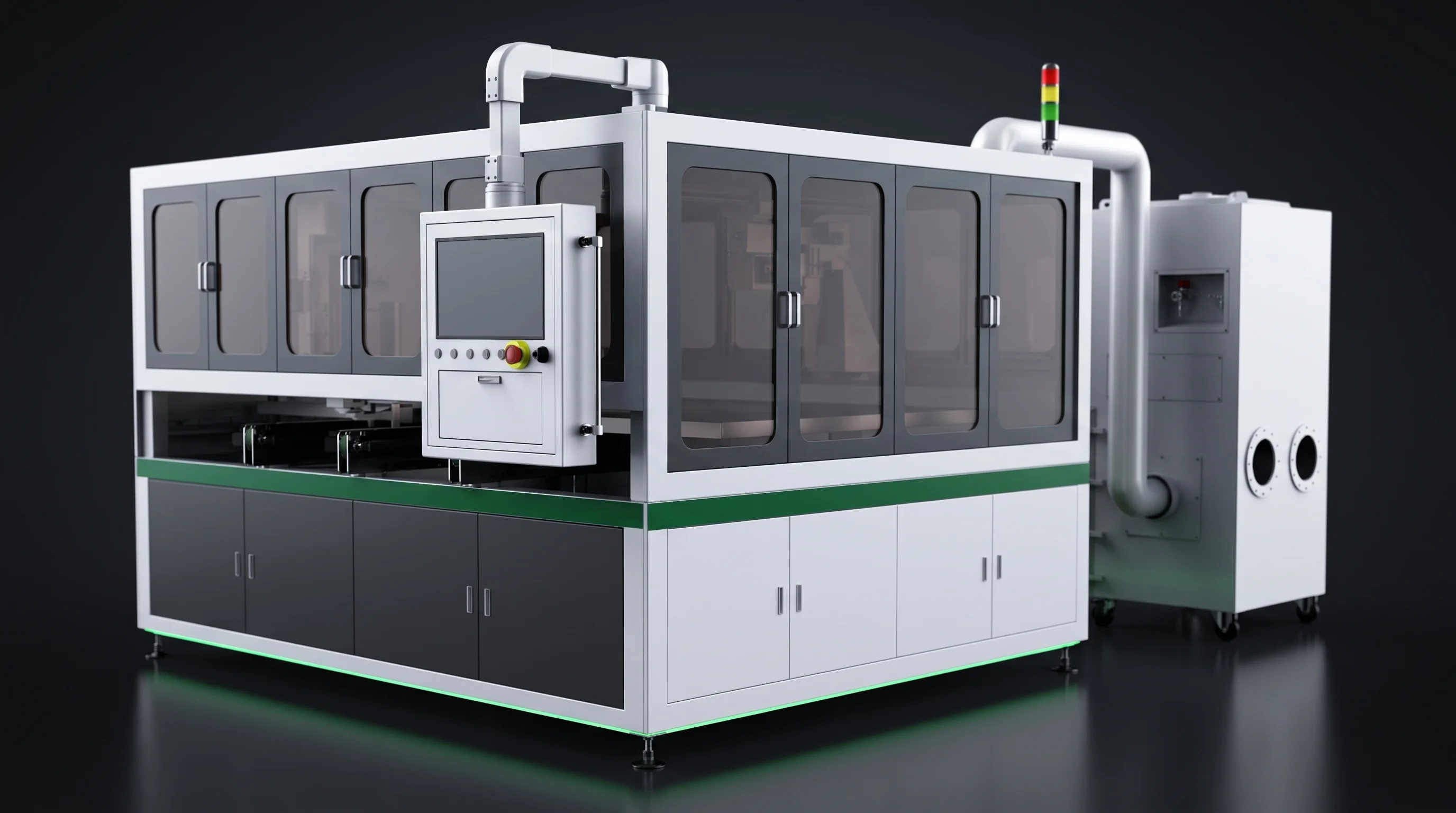
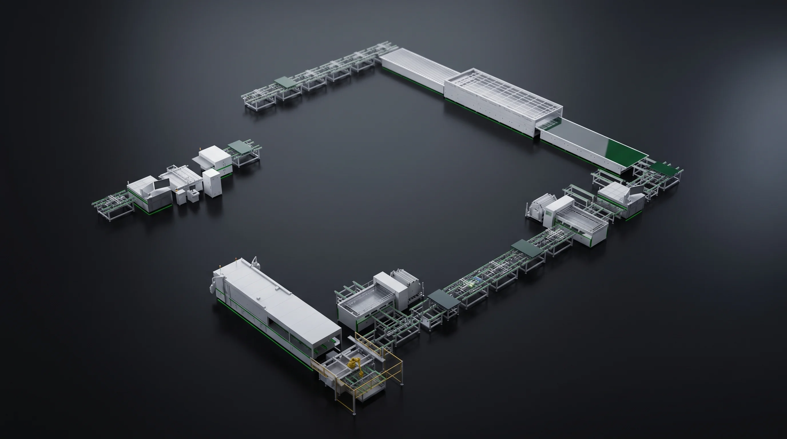
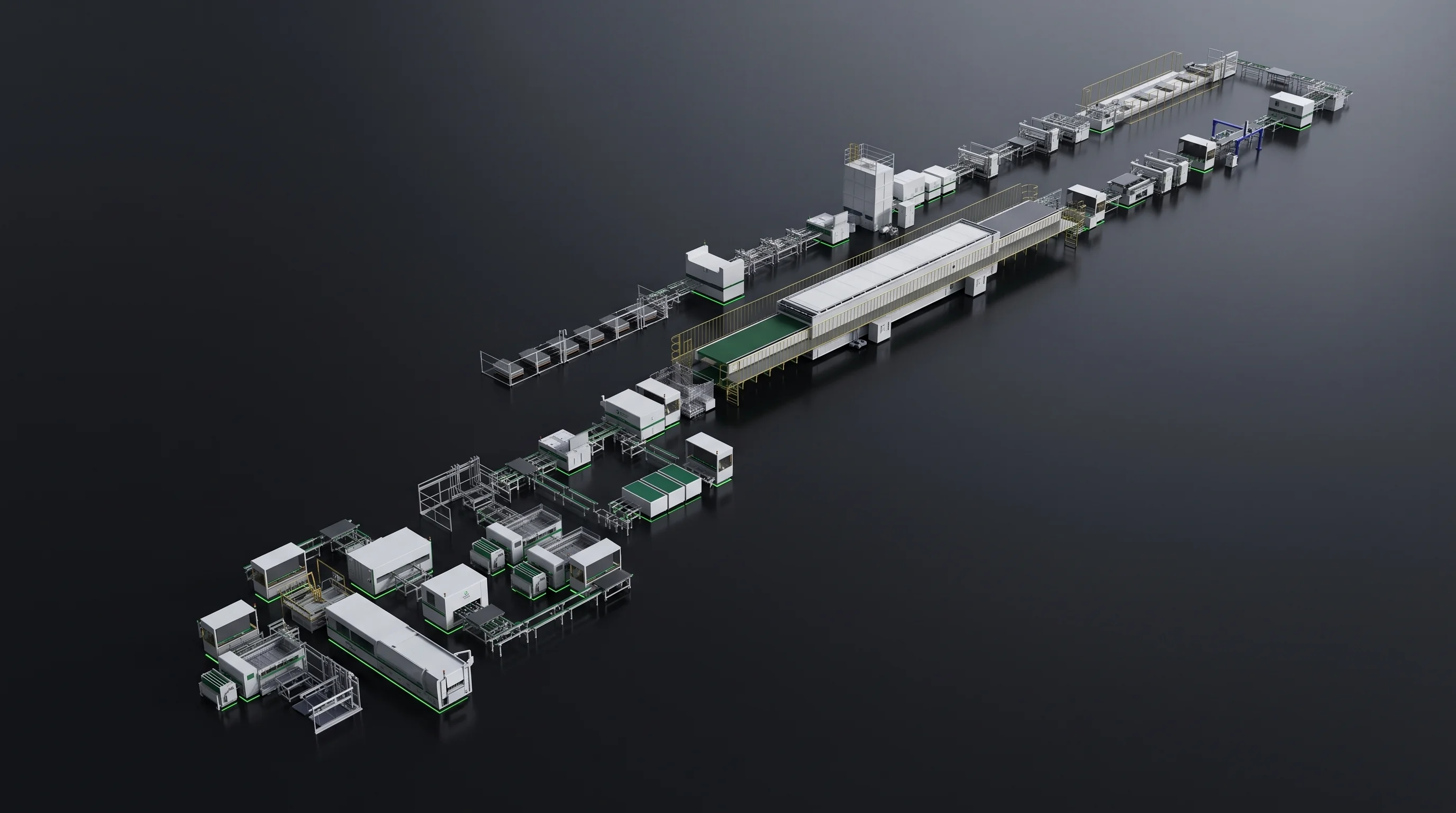
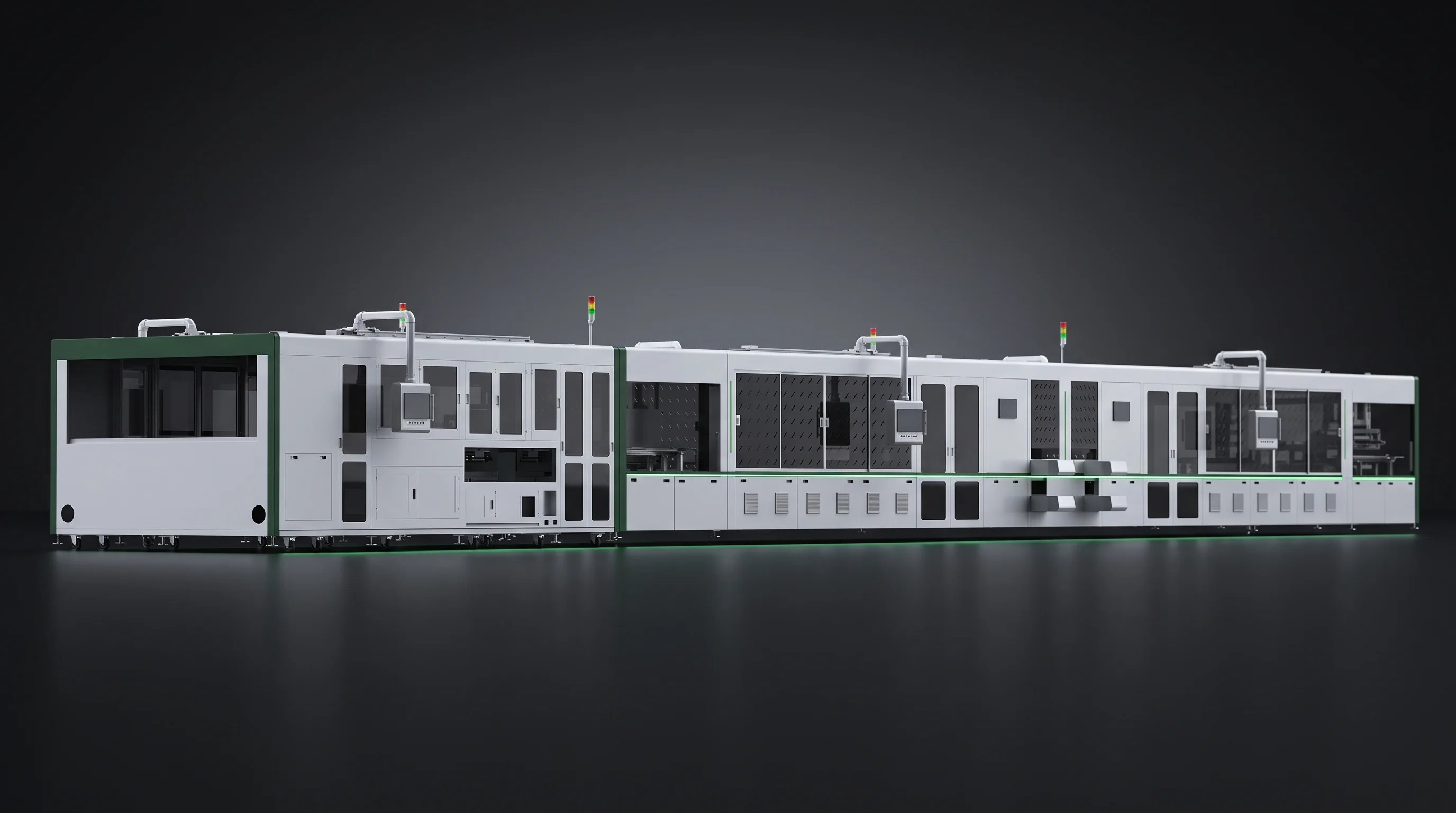
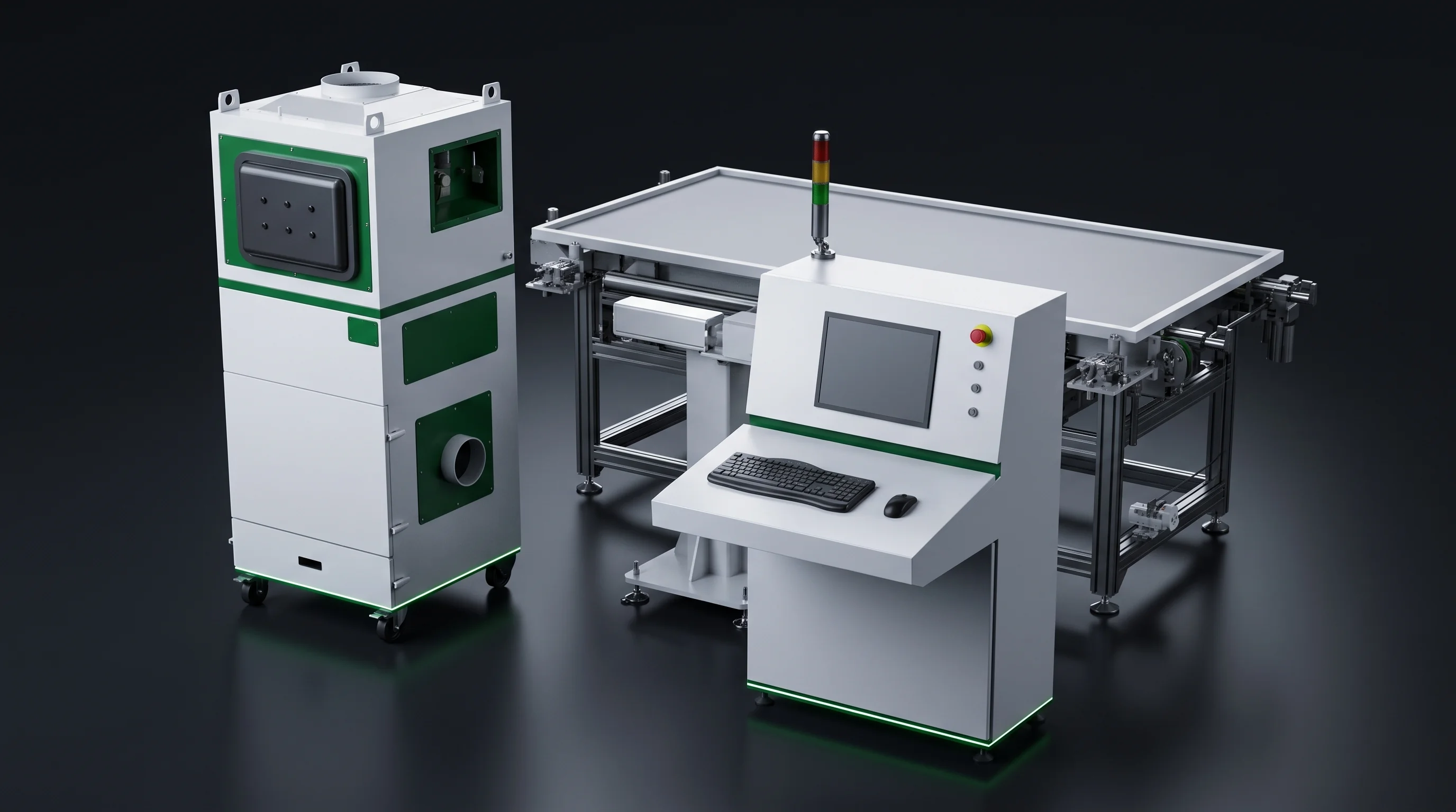
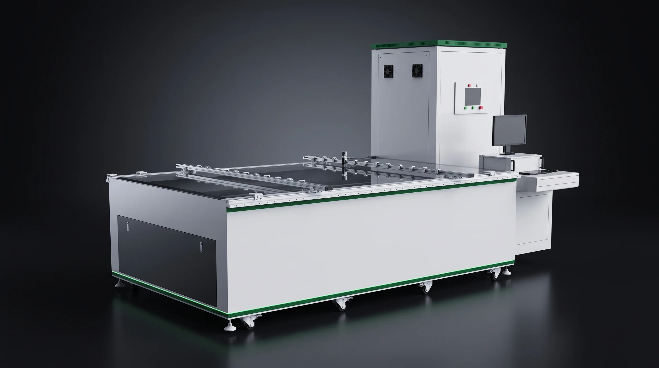
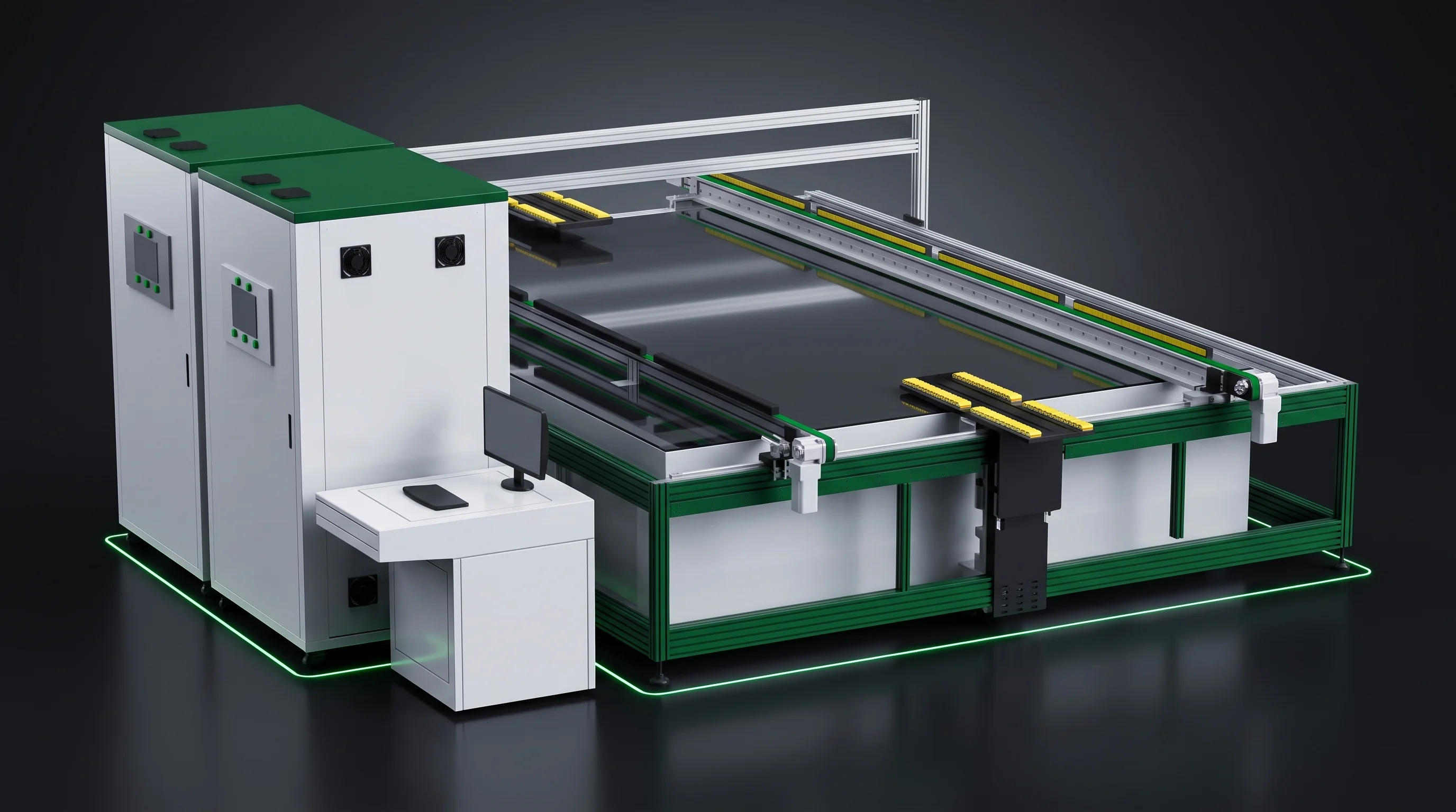
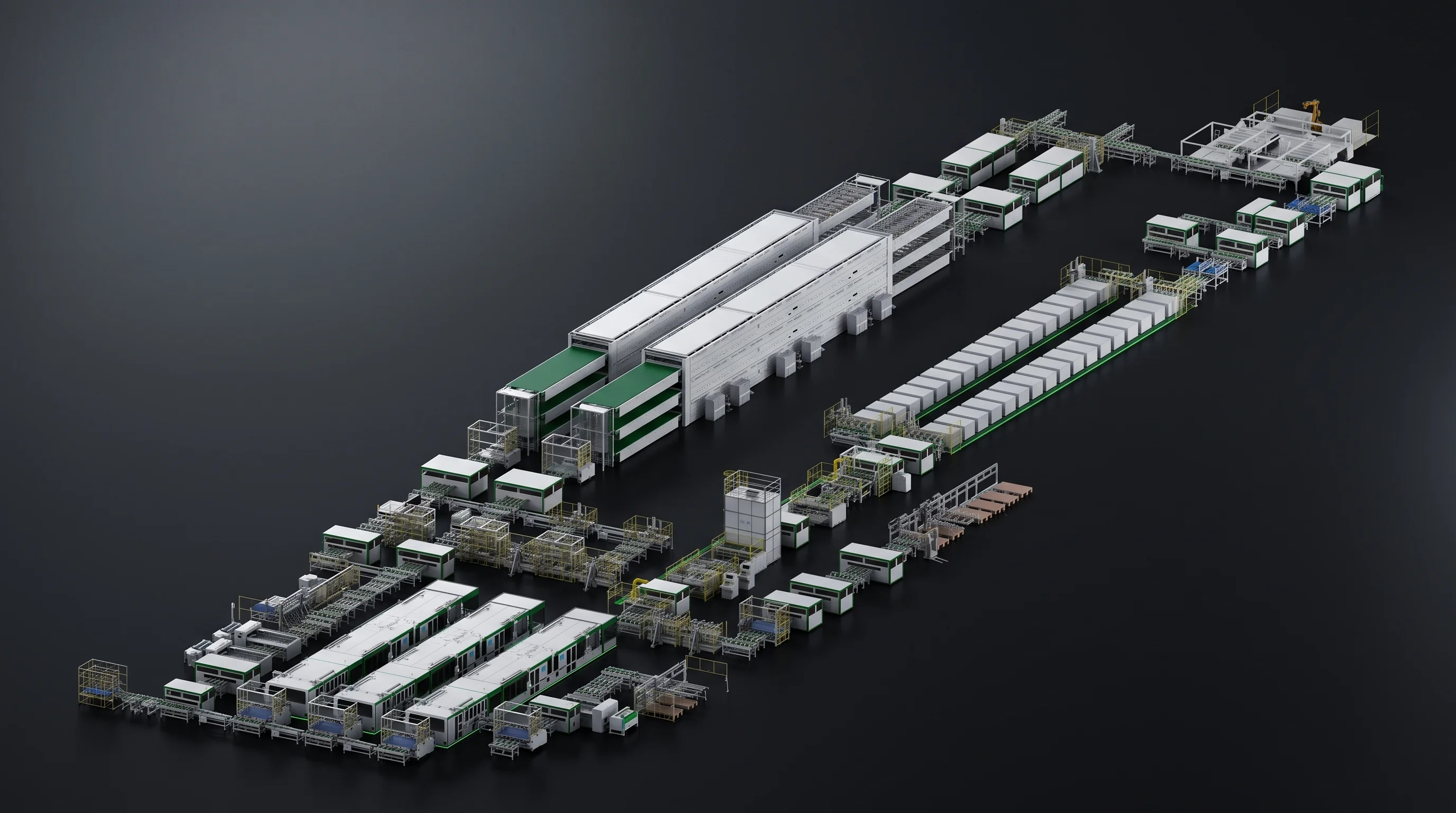
Two module assembly rows standing side by side under studio light, the near row equipped as a BC module line

Route comparison

Three Places a BC Module Line Differs From a TOPCon or PERC Line

The stringer model, the rated hourly figure the scriber is planned against, and the pool of optional models the stringing station can be filled from. Everything else from cell magazine to frame marking is specified the same way on both routes.

  • · Writing an equipment list
  • · Costing a BC upgrade
  • · Route still open
01 Laser scribing CHANGES SML-C724800 full cells/h SML-C726800 full cells/h 02 Stringing CHANGES SML-S60BC stringer SML-S40 / S15Multi-busbar / entry Optional model poolBC variants differ 03 LayupNO EFFECTSML-A6SAME MODEL 04 BussingNO EFFECTSML-B200SAME MODEL 05 EL and IV testNO EFFECTSML-T / SML-ESAME MODELS 06 Frame markingNO EFFECTSML-M200 / M150SAME MODELS
Two stations split by route · four stations shared · one change sits inside station 02

Swipe the route map

What the route decides

Three Things a BC Module Line Changes

Everything below this line is the same on both routes: the station order, the interface heights, the site figures and the acceptance procedure.

3

Three things change when a plant builds a BC module line instead of a TOPCon or PERC one, and each is decided at a different moment: one at order time, one when the schedule is written, one when the model list is drafted.

01 The stringer
SML-S60 BC tabber stringer, the stringing station of a BC module lineSML-S60

A different machine in the row

  • A different machine in the row, not a different setting inside one machine.
  • Fixed at order time, because each machine ships against one blueprint. BC on the SML-S60; TOPCon and PERC on the SML-S40 or the SML-S15.
Decided at order time
02 The rated figure
SML-C72 lossless laser scriber, the same machine on a BC module line and on a TOPCon or PERC lineSML-C72

Same machine, two rated figures

  • Two rated hourly figures on one machine: 4800 full cells per hour or better on BC, 6800 or better on TOPCon and PERC in dual line.
  • Nothing about the machine list changes here — what changes is the number the schedule is built on.
Rewrites the schedule, not the list
03 The model pool
SML-S25 BC stringer, one of the optional models a BC module line can draw its stringing station fromSML-S25

A different pool to fill the station from

  • Six models carry published parameters. Beyond them the range holds further stringers and scribers.
  • Which of them are BC variants and which are conventional depends on the route being equipped.
Names the candidates, not the stations

Those three are the whole list. The site requirements, the interface heights and the acceptance mechanism are identical on both routes. A route decision reshapes part of the equipment list. It does not reshape the line.

Station by station

BC Module Line Station List, Route by Route

Six stations in process order, marked for what the route decides and what it leaves alone. Two rows change, four rows do not, and the fourth column carries the whole reading.

  • Route changes this row
  • Route has no effect on this row
StationBC routeTOPCon and PERC routeRoute effect
Laser scribingSML-C72, rated 4800 full cells per hour or betterSML-C72, rated 6800 full cells per hour or better, dual lineRated figure
StringingSML-S60SML-S40 or SML-S15Different machine
LayupSML-A6SML-A6No effect
BussingSML-B200SML-B200No effect
EL and IV testSML-T450, SML-T500, SML-T1000, SML-T-BIPV, SML-ESame modelsNo effect
Frame markingSML-M200 inline or SML-M150 externalSame modelsNo effect

Swipe the table

The third change does not get a row of its own. It sits inside the stringing row, in the list of models that station can be filled from, and it is set out further down this page. Read the table as two marked rows plus one marked list.

Reading the fourth column

  • Rated figure. The machine list does not move. What moves is the number the production schedule is built on, and it moves by around 42 percent, so a schedule carried across routes is wrong in one direction or the other before a single cell is loaded.
  • Different machine. A line item is replaced, not adjusted — fixed at order time, carrying its own footprint and draw, and no tooling change on the machine already installed reaches it.
  • No effect. Licence to leave that row alone — models, interface heights and acceptance procedure all read the same on both routes.
Straight-run module line where only the stringing bay changes between a BC module line and a conventional oneSame row, two routes

Four rows read the same on both routes

Layup takes a finished string and does not ask which cell technology produced it. Bussing, testing and marking work on a finished laminate stack — the route decision is already spent by the time material reaches them, which is why the models, the interface heights and the site figures behind those four rows carry straight across. On an equipment list that is the practical half of the answer: four of six line items are written once and quoted once, whichever route the plant lands on.

· Same models· Same interfaces· Same site figures

Change 01

The Stringer Is the One Machine That Swaps

Same bay, same handover height, two different frames. Drag the handle across the photograph to move the stringing station between routes.

SML-S40 multi-busbar stringer standing in the stringing bay of a TOPCon or PERC line
SML-S60 BC tabber stringer standing in the same bay on a BC module line
SML-S60 · BC SML-S40 · TOPCon / PERC

Drag to swap the stringing station

Why it cannot be a setting

Every machine ships against one blueprint cell the buyer signs, and within its compatibility range it moves to another busbar count or cell size by fitting the matching tooling. What it does not change is the way it picks up, holds and solders a cell — exactly what separates a back contact cell from a front-contact one.

So the stringing station is chosen, not configured.

SML-S15 entry stringer, the low-volume option on the TOPCon and PERC routeSML-S15 entry
ReadingSML-S60SML-S40SML-S15
RouteBCTOPCon and PERCTOPCon and PERC
Rated output4800 half cells per hour or better3400 per hour or better at 3 to 12 busbars, 3200 at 13 to 201100 half cells per hour
Cell pitchMinus 1 to minus 0.5 mm and 1 to 5 mm1 to 5 mm1 to 5 mm
Pull force0.5 N or better on 0.6 mm flat ribbonFront 0.5 N or better, back 1 N or better on 0.4 mm ribbon0.5 N or better on 0.7 mm flat ribbon
Ribbon feeding20 motor sets, steppable to 25 busbars3 to 20 busbars, 25 reachable by stepping up12 motor sets, upgradable to 20 grids
Cell handlingMagazine holding 200 small cellsFive magazine groups at 300 small cellsSponge flux bath fed by a 10 litre tank with a low-level alarm

Swipe the table

One row in that table is a route boundary rather than a specification difference. Cell pitch is the row that no tooling change reaches, and the next section is about it.

Where tooling stops

Negative Pitch Is Bought, Not Fitted

Most format changes on this equipment are tooling changes. Pitch below zero is not one of them.

Two ranges, one boundary

The SML-S60 sets pitch from minus 1 to minus 0.5 mm as well as from 1 to 5 mm positive, holding either to 0.3 mm. The SML-S40 and the SML-S15 hold the same 0.3 mm, but their range starts at zero.

  • Inside the tooling boundary. Another busbar count or cell size within the compatibility range is reached by swapping the matching tooling, charged separately, and the machine keeps running the work it was built for.
  • Outside it. Pitch below zero belongs to how the SML-S60 places and holds cells, so it is bought with the machine rather than fitted to a machine later.
Soldering head and tooling of the SML-S60, the stringer a BC module line uses for negative cell pitchCells held face down
Positive pitch · all three stringers Cells sit apart. 1 to 5 mm, held to 0.3 mm. +1 to +5 mm gap Negative pitch · SML-S60 only Cells overlap. Minus 1 to minus 0.5 mm, held to 0.3 mm. −1 to −0.5 mm overlap Bought withthe machine NOT FITTED LATER
Positive pitch is a gap between cells. Negative pitch is an overlap, and only the SML-S60 places one.

One thing to check early. If the module design relies on cells overlapping into negative pitch, the stringing station has to be the SML-S60 from the order onward. If the design stays at positive pitch, all three stringers cover it and the choice returns to rated output, busbar count and cell thickness.

SML-I150 combined scribing and stringing machine under studio light

Still choosing the route

Send Both Cell Formats and We Mark What Moves

01 Cell drawingSigned, for each format you are choosing between.
02 Busbar countAnd whether cells are half or third cut.
03 Target outputAs modules or as cells per hour, counting basis stated.

Change 02

One Scriber, Two Rated Figures

The SML-C72 appears on both routes unchanged. One figure in its parameter table reads differently, and it is the figure the production schedule is built on.

Full cells per hour, rated BC route 4800 TOPCon and PERC route, dual line 6800 +2000 per hour 02000 40006000
Same laser set, same cell window, same breakage figure. The rated line is the one that forks.
42%

The second figure sits around 42 percent above the first, and both belong to the same machine. Read the stringer figure separately: the scriber counts full cells entering the machine, the stringer counts the half cells it strings.

Everything else in the table is shared

  • Laser set. 60 W for grooving, 300 to 500 W for thermal cleaving, 20000 hour warranty.
  • Quality. Breakage 0.05 percent or better on A-grade cells, positioning within 0.05 mm.
  • Cell window. 166 by 166 to 210 by 210 mm at 120 to 220 micron.
  • Process. Water-cooled groove, deionised or purified water cleave, NG rejection at load and unload.

Take each route on its own figure. A BC schedule carried onto a TOPCon blueprint leaves the scriber under-planned, and the reverse over-plans it.

SML-C80 lossless scriber variant, part of the scribing pool a BC module line can draw fromSML-C80 variant

At entry volumes

The SML-C20 covers the conventional route at 1600 full cells per hour or better, 156 by 156 to 220 by 220 mm, with standard cleaving tooling for 166 to 182 mm two-cut work.

What the route never touches

Angle within 0.04 degrees, scribing speed to 500 mm per second and Bernoulli pick-up on the entry machine are written once and read the same on both routes.

SML-C20 entry laser scriber, the low-volume scribing option outside a BC module lineSML-C20 entry scriber

Shared ground

Cell Windows Do Not Fork by Route

The one difference in the list below is between two machines, not between two routes.

Cell thickness window, micron SML-S60 SML-S40 SML-S15 SML-C72 SML-C20 110120 200220
One step at 120 micron, one step at 200. Neither of them is a route boundary.

Three readings that carry across both routes

  • Thickness. The SML-S60 and the SML-S40 both run 110 to 200 micron. The SML-S15 runs 120 to 200. The SML-C72 and the SML-C20 both run 120 to 220.
  • Busbar coverage. 3BB to 20BB across all three stringers, 25BB reachable on the SML-S60 and SML-S40 by stepping the ribbon feeding motor sets up.
  • Cell size. 166 to 210 mm on the SML-C72 and all three stringers, and 156 by 156 to 220 by 220 mm on the SML-C20.

Breakage carries a thickness condition rather than a route condition: stringing holds 0.25 percent or better on A-grade cells, measured at 120 micron and above on the SML-S60 and the SML-S15 and at 110 micron and above on the SML-S40.

SML-C20B lossless scriber variant, running the same cell window on both routesSame cell window

When two routes are compared on paper, compare stringer pitch, stringer rated output and the scriber rated figure. Thickness, busbar count and cell size are shared ground.

Change 03

BC Module Line Model Pool and Variants

Six models carry full technical agreements and their parameters are published. A BC module line draws stringing from the SML-S60 and scribing from the SML-C72; a TOPCon or PERC line draws stringing from the SML-S40 or SML-S15 and scribing from the SML-C72 or, at entry volumes, the SML-C20.

Beyond the six published models

  • BC side. The SML-S25 BC stringer and the SML-S15B and SML-S60B BC stringer variants.
  • Conventional side. The SML-S72 high-speed stringer, sitting alongside the SML-S40.
  • Shared. The SML-C80 and SML-C20B lossless scriber variants, the SML-C800 for wafers, and the SML-I150, SML-I150L and SML-L150 combined frames. The parameter table for each arrives with its technical agreement when it is selected.
SML-S15B BC stringer variant in the optional model pool of a BC module line
BC sideSML-S15BBC stringer variant, selected when the stringing station is filled on a back contact route.
SML-S72 high-speed stringer on the conventional side of the model pool
ConventionalSML-S72High-speed stringer sitting alongside the SML-S40 on a TOPCon or PERC route.
SML-C800 laser scriber for wafers, part of the scribing pool both routes can draw from
ScribingSML-C800Laser scriber for wafers, shown by name and appearance alongside the C80 and C20B variants.
SML-I150 combined scribing and stringing frame serving a BC module line and a conventional line alike
Both routesSML-I150Joins scribing and stringing in one frame, cutting two positions on the floor into one.
SML-I150L combined scribing, stringing and layup frame
Both routesSML-I150LAdds layup to that frame, so three process positions arrive as one machine.
SML-L150 combined module layup and welding frame
Both routesSML-L150Combines module layup and welding in a single frame downstream of stringing.

That is the third change, and the mildest. It does not alter the shape of the line or the stations it is built from — it alters which named models are candidates when the stringing station is filled.

No effect

Layup, Bussing, Test and Marking Stay Put

Downstream of stringing the route stops having an effect, because what the layup robot picks up is a finished string.

SML-A6 robotic layup station taking finished strings from either stringer on a BC module lineSML-A6
Layup

SML-A6 robotic layup

Modules 1650 to 2500 mm long and 990 to 1450 mm wide at 6 seconds or better per string, placing to 0.5 mm with CCD positioning, docking to the stringer at 1230 mm.

SML-B200 automatic busbar welding machine standing downstream of layupSML-B200
Bussing

SML-B200 busbar welding

Takes the laid-up stack after layup. Specified identically on both routes.

SML-E EL tester reading finished laminates on both routesSML-E
Test

SML-E EL tester

Electroluminescence inspection of the finished module, on the same model whichever route produced the strings.

SML-T450 IV tester, the first of three power levels on both routesSML-T450
Test

SML-T450 IV tester

First of three power levels, joined by the SML-T-BIPV for BIPV modules.

SML-T1000 IV tester at the top of the three power levelsSML-T1000
Test

SML-T1000 IV tester

Top of the three power levels, with the SML-T500 between. All three are specified against module power, not cell technology.

SML-M200 inline frame marking machine at the end of the rowSML-M200
Marking

SML-M200 inline marking

Inline on the SML-M200 or external on the SML-M150. The same two models close the row on both routes.

Given on both routes

  • Cell-level defect detection is built into the stringer on both routes.
  • It reads chipped corners, edge chipping, cracking and printing skew, with thresholds defined at the host computer.

Chosen, not given

  • String appearance inspection and string EL inspection are optional on the SML-S60.
  • String EL reads virtual solder joints and micro-cracks, and is specified when the machine is ordered.
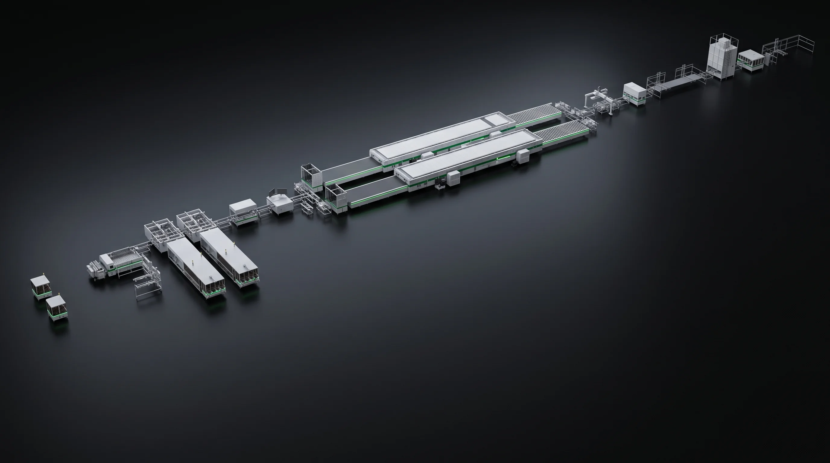
U-shaped module line layout, unchanged by the cell technology it runs

A route decision reshapes part of the equipment list. It does not reshape the line.

What it costs to switch later

Site

Floor and Utilities Stay Put

Supply, compressed air quality, exhaust, floor load and ambient conditions are written per machine and are unchanged by the cell technology, and so are the two interface heights the row hands over at.

One bay to re-check

What does move with the stringer choice is the footprint and the draw of that one frame. The SML-S60 measures 8050 by 2800 by 2500 mm at 7000 kg and averages 30 kW with a 45 kW peak on one side. The SML-S40 measures 7850 by 1600 by 2500 mm at 4500 kg and averages 40 kW with a 60 kW peak. The SML-S15 measures 6900 by 1800 by 2300 mm at 3000 kg and averages 15 kW.

Air and exhaust follow the same pattern: the SML-S60 and SML-S40 each take two 16 mm hoses, the SML-S15 one. The judgement is narrow — keep the floor plan and the utility design, re-check the bay the stringer stands in.

· 600 kg/m² floor load· 0.6 to 0.8 MPa air· 5 to 40 °C
STRINGER FOOTPRINT, TO SCALE SML-S60BC 8050 × 2800 mm7000 kg · 30 kW avg SML-S40TOPCON / PERC 7850 × 1600 mm4500 kg · 40 kW avg SML-S15TOPCON / PERC 6900 × 1800 mm3000 kg · 15 kW avg
Three frames drawn against one wall line. Only the bay depth changes with the route.
L-shaped module line floor plan, unchanged when the stringing bay moves to a BC module lineFloor plan stands

Adding BC to a running floor

Switching to a BC Module Line Later

Plants running TOPCon or PERC today often ask what a move to a BC module line costs them in equipment already bought. Read it against the same three changes, position by position.

  • Re-equipStringingAn SML-S40 or SML-S15 already on the floor keeps running the route it was bought for, and BC work needs an SML-S60 or one of the BC stringer variants added or substituted at that position. Where the old stringer stays in service on a second row, the interface figures are unchanged, so the layup station behind it accepts strings from either.
  • Carries overScribingThe SML-C72 already installed is the machine a BC module line uses. What changes is the rated figure the schedule reads for it, from 6800 full cells per hour to 4800. No mechanical change is involved in that. What the new format does call for is tooling, because the machine ships against one blueprint and cells of another format or grid count inside its compatibility range are run with the matching tooling fitted, charged separately.
  • Carries overLayup, bussing, test, markingFour positions carry over without change, and so does the site.
SML-I150L combined frame, one route to re-equipping a stringing position on an existing lineOne position, three processes

What the conversation shrinks to

Three questions rather than a line: which stringer goes in, what tooling the new format calls for, what the scriber schedule is rewritten to.

Send the cell drawing for the BC format you are moving to and the model already installed at each position, and that list comes back as machines and tooling rather than as a whole line.

How it is signed off

Acceptance Reads the Same Table

Each machine ships against the single blueprint you define, and the parameter table of its technical agreement is the acceptance standard — on a BC module line exactly as on a TOPCon or PERC one.

01
Run-off before shipment on your blueprint cell, with the parameter table read item by item.
02
Installation and commissioning by our engineers on your floor.
03
Free training before acceptance, at least once and at most twice.
04
One free warranty year with lifetime repair service, response within 48 hours of written notice and a solution within 72.

A BC order is read against

The SML-S60 parameter table and the 4800 full cells per hour figure of the SML-C72.

A TOPCon or PERC order against

The SML-S40 or SML-S15 table and the 6800 figure of the same SML-C72.

SML-M150 external frame marking machine, accepted against the same parameter table on both routesSame procedure
Same document, same procedure, different rows. The one route-linked item is which table is being read.

Inputs

Seven Readings for a Route Map

To get a station-by-station map rather than a general answer, seven readings do the work.

  1. The cell drawing with the signature on it.
  2. The route you are planning for, or both if it is still open.
  3. Cell size and busbar count.
  4. Half or third cut, stated rather than implied.
  5. Cell thickness in micron.
  6. Target output with its counting basis stated, modules or cells per hour.
  7. Whether the module design uses negative cell pitch.

Adding BC to a floor that already runs

Add the models installed at each position today, the string length in use and the handover height of the existing row.

A station list with the route effects marked comes back within 24 hours. After an order is signed, the production cells and string information are due within 5 to 10 working days so tooling can be cut.

SML-T500 IV tester, one of the positions that needs no rework when a line moves to BCUnchanged position
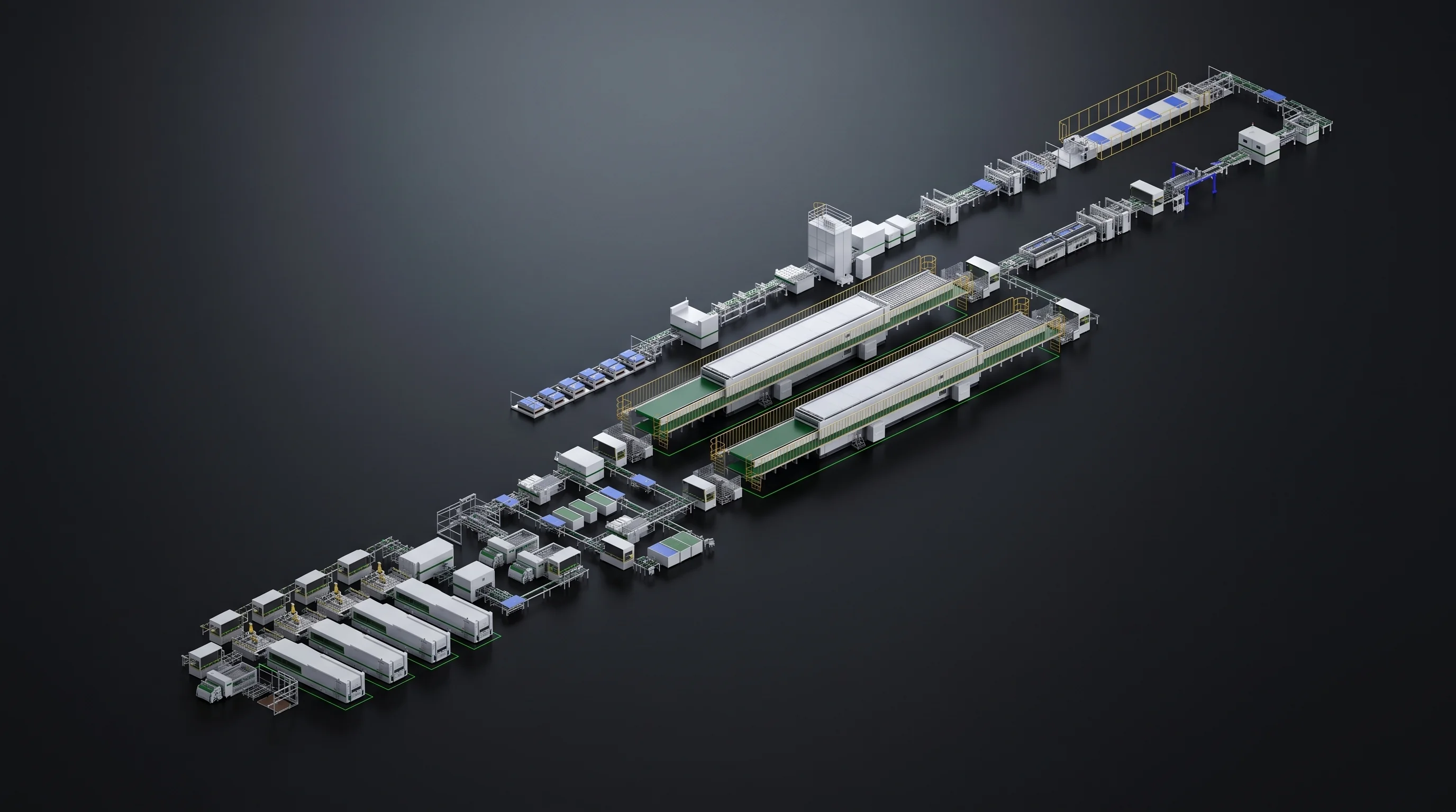
Complete BC module line seen in isometric view under studio light

Get your route mapped

Cell Drawing, Route, Busbar Count, Target Output

Put those four in one message and a station list marked change by change reaches you within 24 hours.

What comes back
Station list with the route effect marked on every row
If the route is open
Send both cell formats and we mark the stations that move

How to reach you

[email protected]