
Entry stringer
SML-S15 Entry Stringer — Built for the Entry Tier, Not Cut Down From a Bigger Machine
The entry stringer for TOPCon and PERC — 1100 cells an hour on the same positive-pitch route the faster machines run, engineered for a first line or a single added string.
Entry · this machine
1100
pcs/h · SML-S15
Standard
≥3400 / ≥3200
pcs/h · SML-S40
High-speed
≥4800
pcs/h · SML-S60
You pick the tier by the line you're building, not by a grade — and at the entry tier this is the specialist, on the same 166–210 mm half cells.
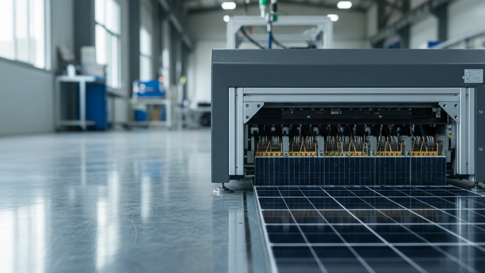
TOPCon & PERC half cells in → strings out, at 1100/h
Where it sits
Where This Machine Sits
Two machines share this exact station on the TOPCon and PERC route — the SML-S15 and its faster sibling, the SML-S40. Where each sits is identical; the divider is scale.
Same Station as the SML-S40 — Smaller Scale
What divides the two is not the station but its scale, and it reads off two numbers: the SML-S15 carries 12 feed sets and draws 15 kW, against the SML-S40's 20 feed sets and 40 kW on the very same route.
Settle the in-feed early
The machine expects cells already separated at scribing. If your upstream still snaps cells over an edge, watch the join between scriber and stringer — not the stringer itself. Anything upstream of scribing or downstream of layup falls to other machines, each on its own page here.
Who it's for
Who This Machine Is For
You are on this page if the line you're building is your first, or a single string added to one — the entry-scale build. The split below tells you whether the SML-S15 is your machine, or whether the faster S40 already fits your numbers.
Built for this machine
- TOPCon and PERC cells, 166–210 mm — half or third cells on the positive-pitch route.
- A first line or a single added string — 1100 cells an hour is the cadence a starter line or a capacity top-up runs at.
- 3BB–20BB busbars — 12 feed motors now, with headroom to 20 busbars as the string grows.
- Cells 120–200 μm — thin-capable; the ≤0.25% chipping floor holds from 120 μm up.

Where to go instead
- Higher throughput on the same route — the SML-S40 is the multi-busbar stringer for TOPCon and PERC at ≥3400/≥3200 pcs/h.
- The BC route — the SML-S60 is the BC stringer, built for negative pitch.
None of the three is a grade of the others — each is the stringer for its own tier, and the SML-S15 owns the entry step: a first line or an added string. If that is the scale you're building to, this is the page; if your volume is already past it, the faster frames start where it ends. To place all three by tier, route and cadence, line the three stringers up on the tabber-stringer page →
Full spec
Full Specification
This is the checklist your process team runs against the drawing on your desk — the sections that follow explain the numbers, this one lists them.
The entry stringer earns its place on one number — 1100 cells an hour — so read that row first, then work down against the cell format you'll sign for.
| Parameter | Value |
|---|---|
| Cell | |
| Applicable cell | TOPCon / PERC, 166–210 mm, half / third cell |
| Busbar count | 3BB–20BB |
| Cell thickness | 120–200 μm |
| Throughput | |
| Capacity | half-cell 1100 pcs/h |
| Utilization | ≥95% |
| Chipping rate | ≤0.25% (A-grade)Holds at ≥120 μm; rises on ultra-thin cells. |
| Precision | |
| Positioning accuracy | ≤±0.1 mm; angle ≤±0.04° |
| Transfer-module placement | ±0.02 mm |
| Conveyor accuracy | ±0.01 mm |
| Cell pitch | positive 1–5 mm |
| Welding | |
| Method | infrared; flux by left-side sponge soak tank |
| Weld pull force | ≥0.5 N (0.7 mm flat ribbon; suits 0.6–1.0 mm) |
| String defect rate | ≤3% |
| Overlap-return rate | ≤15% |
| Feeding | |
| Ribbon feeding | 12 feed motors, upgradable to 20 busbars |
| Flux supply | sponge soak tank; flux tank with low-level float alarm, ~10 L |
| Power & utilities | |
| Power | avg 15 kW, peak 20 kW |
| Supply | 3-phase 380 V / 50 Hz; feed 4×10 + 1×6 mm² |
| Air | ≥600 L/min; single φ16 mm hose |
| Exhaust | top φ102 mm; >300 m³/h |
| Footprint | |
| Dimensions | 6900×1800×2300 mm |
| Weight | 3000 kg |

Flux sponge soak tank

Transfer module & conveyor
Flux, held steady
Where the Entry Machine Keeps Flux From Drifting
A joint is decided before the infrared pass ever runs — reach the pad with flux carried unevenly, and the weld forms cold in places no operator sees. So the machine puts its effort where the defect is born, not where it's found.
Sponge Soak, Not Spray
Flux is carried by a left-side sponge soak tank: the ribbon passes through a fluxed sponge so it takes flux up evenly along its length, rather than by a spray that can thin out or run dry across a cell. Even coverage here is what keeps every joint on the string forming under the same condition — the single biggest lever an entry machine has over cold solder.
The Slow Failure: a Draining Tank
The failure mode a soak tank has is a slow one. The flux level falls as the shift runs, and a tank left to drain fluxes the last cells more thinly than the first, with no visible change at the weld. That is exactly the drift that shows up as scattered cold joints at EL, a batch at a time.
A Float Alarm on a 10 L Reservoir
So the flux tank carries a float-type low-level alarm, on a reservoir of about 10 L. The alarm turns a silent drain into a caught event: the level reaching its floor raises a warning before the tank fluxes a run of cells too thinly, so the operator tops it up on a signal instead of finding the shortfall a string later at inspection.
A pull-force floor of ≥0.5 N on the 0.7 mm ribbon still backs the weld — but the alarm is what keeps that floor from being quietly undercut between checks. On an entry line running one shift at a time, that is the difference between a flux tank you watch and one that watches itself.

Three moves
Flux, Weld, Then Carry
The entry stringer runs three moves in order, and each hands a settled cell to the next. Run them out of order and the weld inherits a step that was never finished.
Flux by sponge soak
The ribbon takes flux up evenly at the left-side soak tank, so every joint forms under the same flux condition — not a spray that can run thin.
Infrared welding
The fluxed ribbon is brought onto the pads and the joint forms under infrared heat, on the ≥0.5 N pull-force floor.
Carried by the transfer module
The placed cell is moved on by a transfer module holding ±0.02 mm, on a conveyor accurate to ±0.01 mm, so the string keeps its geometry cell after cell.
The third move is the one that separates a steady entry machine from a merely cheap one. A weld made well is only kept well if the cell is then carried without being nudged.
Holding the carry to ±0.02 mm is how the string that leaves the machine looks like the string that was welded.
Sponge soak
±0.02 mm carry
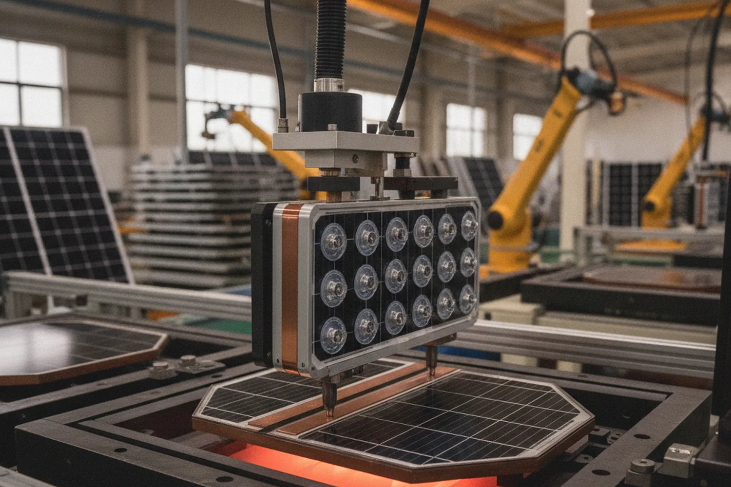
The numbers
The Three Numbers Behind the Entry Line
These are the numbers your entry line is signed against — the cadence, the placement, and the string floor. No reading required; glance and you know the tier.
1100
pcs/h — half-cell throughput, the entry cadence
≤±0.1 mm
Positioning accuracy · angle ≤±0.04°
≤3%
String defect rate · overlap-return ≤15%
The throughput figure is the tier from the top of the page, restated as the signed floor: 1100 cells an hour is the rate the acceptance table holds the machine to. String defect rate sits with overlap-return at ≤15%, and both are read against the drawing you sign, not a datasheet average.
Carry & placement
How the Cell Is Carried and Placed
Placement here is a two-part number. Comprehensive positioning holds ≤±0.1 mm with angle ≤±0.04°; underneath it, the transfer module places to ±0.02 mm and the conveyor runs true to ±0.01 mm.
- 1
Positioning puts the busbar under its ribbon
The ≤±0.1 mm figure is where each cell lands — enough to bring the busbar under the ribbon so the joint forms on contact, not half off the pad.
- 2
Transfer and conveyor keep it there
The ±0.02 mm transfer and ±0.01 mm conveyor are how the cell gets to the next station without drifting. A machine that places well but carries loosely lands the cell right, then lets it wander before the weld sets — the tighter carry figures close that gap on an entry frame.
- 3
Angle carries the outer busbars
A small rotation that looks harmless at the cell center throws the outer busbars furthest off their ribbon, so the ≤±0.04° angle limit keeps the edge pads landing as true as the middle ones, string after string.

Tier boundaries
One Tier, by Design — the Feed and Thickness Boundaries
Two boundaries are worth settling before the machine lands, because both are tier decisions, not shortfalls. The SML-S15 is built and accepted to the one entry-line format you sign.
Its feed and thickness ranges are set for the entry tier — with real headroom inside that tier, and clear edges where a bigger-tier frame takes over.
What this machine runs
- 12 feed motors, to 20 busbars — sized for the entry tier, with headroom to 20 as the string grows, each motor selectable at the host.
- One signed blueprint — built and accepted to the entry-line cell format you provide, other formats in range handled by changeover.
What sits outside it
- Cells thinner than 120 μm — the chipping floor holds from 120 μm up, a slightly higher floor than the faster machines; cut below it and that's a route to check with us.
- Busbar counts past 20 — the 25BB headroom belongs to the higher-tier frames; 20 is this machine's ceiling, by design.
How the entry-line tooling changes when you step busbars or swap cell size, and how that change is quoted, has a page of its own. Plan it on the compatibility and changeover page → before you step busbars or change size.
Its neighbors
What It Hands To, and Takes From
An entry stringer sits between two neighbors, and each has a page of its own — one line here, the rest a click away, so the interface is settled before the crate ships.
-
Out-feed to layup
Strings hand to a robotic layup machine, or the stringer runs standalone; the docking height lives on the SML-A6 layup page.
See layup -
In-feed from scribing
The machine takes cells already separated at the scriber; how the cut is made sits on the laser scriber page.
See scribing
Your floor
Measure Your Floor First
Start with power — it is where this machine departs most sharply from its siblings: 15 kW average, 20 kW peak, a full tier below the S40's 40/60 kW and the S60's 30/45 kW, so the electrical supply it needs is a different order of draw.
| Item | SML-S15 |
|---|---|
| Footprint | 6900×1800×2300 mm |
| Weight | 3000 kg |
| Power | avg 15 kW, peak 20 kW |
| Supply | 3-phase 380 V; feed 4×10 + 1×6 mm² |
| Air | ≥600 L/min, single φ16 |
Other stringers
Higher Throughput, or the BC Route?
The SML-S15 holds the entry step. Each of the other two stringers keeps one thing from it and trades another — read what each swaps, and you'll know which page is yours.

SML-S40 — Multi-Busbar Stringer
Keeps the S15's TOPCon and PERC positive-pitch route; trades entry cadence for standard, at ≥3400/≥3200 pcs/h on 20 feed sets. The move when the route holds but the volume climbs.
Compare
SML-S60 — BC High-Speed Stringer
Swaps the route itself — negative-pitch BC in place of the S15's positive-pitch TOPCon and PERC. The page to open only once your cells are BC.
CompareThe three set out side by side by tier, route and cadence — compare all three on the tabber-stringer page →
After you buy
After You Buy
One line of the acceptance test is specific to this machine, and it is easy to sign past — the pull-force floor is tied to a ribbon.
Tie the pull-force floor to a ribbon
The SML-S15's ≥0.5 N weld pull force is measured on 0.7 mm flat ribbon, and the spec holds across 0.6–1.0 mm — so the figure you accept the line against only means something if the ribbon on your acceptance run is the grade written into the technical agreement. Pin the ribbon spec in the agreement, and ≥0.5 N becomes a test you can repeat rather than a number you take on trust.
See how acceptance is run against the agreement
Get a proposal
Get Your Entry-Line Proposal
Send one drawing, get one entry-line proposal back — the low-commitment first step, before anything is signed.
Entry line sized to your route within 24 hours · email.