
Entry Laser Scriber
SML-C20 Entry Laser Scriber — Sized to Fit Where a Line Has No Room
It stands 1500 mm tall on a 1000 × 650 mm floor and weighs 400 kg — the smallest footprint in the whole range, and the one station that runs on a single-phase 220 V supply.
1000 × 650 × 1500 mm · 400 kg — the smallest footprint on this range, on a 220 V single-phase supply.
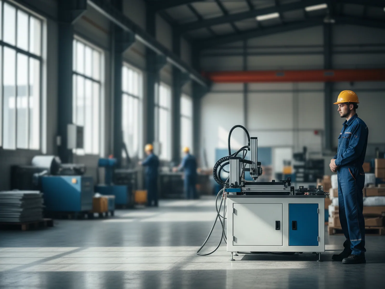 400 kg · 1000 × 650 mm
Where it drops in
Where This Machine Drops In
Know where it drops in before you weigh a parameter. The SML-C20 does one job inside one small box: whole cells in, each one scored and split, separated wafers out — a self-contained cell separator, not a line.
It reads two interfaces only.
| In-feed | whole cells, 156–220 mm, from your cell supply. |
|---|---|
| Out-feed | wafers already separated, handed to the station that takes them next. |
A Self-Contained Separator That Fits a Corner
It is a self-contained cell separator, not a line — which is exactly why it fits a corner. On a modest-throughput line, a pilot cell, or a single station added to an existing floor, a compact scriber that asks only for a 220 V outlet and a metre of floor is often the right size, where a high-speed machine would be over-built.
The Out-Feed Guarantee: a Repeatable Split
What the machine guarantees at the out-feed is a repeatable split — every wafer parted the same way along the scored line — so the station that takes them next works on cut wafers rather than on whole cells it has to part itself, and nothing downstream inherits a split that drifted off the line. Whatever makes the cells upstream is a separate scope this machine never touches.
Who it's for
Who This Machine Is For
The entry scriber is built for a specific tier. The split below places you in a few seconds — not by ranking the two scribers, but by matching each to the line it was drawn for, so you read the right spec sheet the first time.
Built for this machine
- Monocrystalline, PERC and similar cells — 156×156 to 220×220 mm, 120–220 μm thick.
- Modest-throughput lines — around ≥1600 whole wafers an hour, the pace an entry or pilot line runs.
- A single-phase floor — 220 V, 3 kVA, with no three-phase drop to plan for.
- A standard two-way split — 166–182 mm split tooling comes standard; other ratios are settled below.

Not this machine — where to go
- BC full cells at high speed, or a zero-microcrack lossless cut — that is the SML-C72's job, on a different throughput class and a three-phase supply.
- Back-aluminum cells — these fall outside this machine's cell scope; the boundary is stated in full below, not buried in a footnote.
Put the two scribers on one page and the choice is quick: the entry tier for a single-phase line, the high-speed lossless cut for BC volume. See the laser scribing machine page →
Full spec
Full Specification
Your process team will run down this sheet number by number — the laser, the kerf, positioning, throughput and the split, every figure the machine is signed to. The reasons behind the numbers are unpacked in the sections below; here it's the bare list.
One figure needs its basis read with it: ≥1600 wafers an hour is counted as one cut on a 166 mm single wafer. Hold it against your own cell size and cut count, not as a fixed ceiling.
| Parameter | Value |
|---|---|
| Process | |
| Cutting method | laser scribing + automatic wafer splitting (micro-loss) |
| Applicable cell | monocrystalline / PERC and similar, 156×156–220×220 mm (back-aluminum cells excluded) |
| Cell thickness | 120–220 μm (±10 μm within a batch) |
| Split | 166–182 mm two-way split standard; other ratios by custom tooling |
| Throughput | |
| Capacity | ≥1600 whole wafers/h (one cut on a 166 mm single wafer) |
| Breakage rate | ≤0.2% |
| Laser | |
| Type / wavelength | 30 W Q-switched, λ=1064 nm |
| Max cutting speed | 500 mm/s |
| Precision | |
| Scribing accuracy / kerf | ±0.1 mm / 40 μm line width |
| Positioning accuracy | ≤±0.1 mm |
| Handling | |
| Pickup | Bernoulli suction cup (non-contact, non-marking) |
| Max format / module stroke | 226×226 mm / 300×300 mm |
| Utilities | |
| Power | 220 V / 50 Hz / 3 kVA (single-phase) |
| Air | 0.5–0.8 MPa · φ12 mm inlet |
| Dimensions / weight | 1000×650×1500 mm / 400 kg |

Laser head detail

Bernoulli pickup head
Non-contact pickup
Why Thin Cells Ride on Air, Not a Vacuum Cup
A scriber is only as gentle as the hand that loads it, and on a thin cell that hand is the first place a crack can start — long before the laser ever touches the silicon.
How a Vacuum Cup Stresses a Thin Cell
An ordinary vacuum cup grips by sealing a ring against the cell and pulling a partial vacuum inside that ring. On a rigid part that is fine. On a thin, brittle silicon wafer two things go wrong: the seal ring presses on the cell face and can leave a mark or pick up contamination right where it touches, and the pressure difference pulls the cell down onto the sealing edge, flexing it around that rim — and a thin cell flexed over an edge is a cell being asked to crack. You don't see it at the pickup; you find it later, as a hidden-crack reject.
The Bernoulli Lift: Held Without Touch
The SML-C20 never seals a cup against the cell. It lifts with a Bernoulli suction cup: the cup blows a fast, thin sheet of air radially across the cell's top face, and by Bernoulli's principle that moving air drops the pressure just above the cell below the still air beneath it — so the cell is pushed up onto a cushion and held, with no ring pressing down and no rim to flex it over. It is picked without being gripped.
What Non-Marking Pickup Buys You
That is what the spec means by non-marking pickup: nothing hard touches the working face, so there is no seal mark, no contamination ring, and no edge for a thin cell to break against. The thinner the cell, the more a contact grip costs you — and the more a non-contact lift is worth.

The evidence is the number the machine is signed against: breakage held to ≤0.2% — and it starts here, at the way the cell is first touched.
Load, scribe, split
Load, Scribe, Split — in That Order
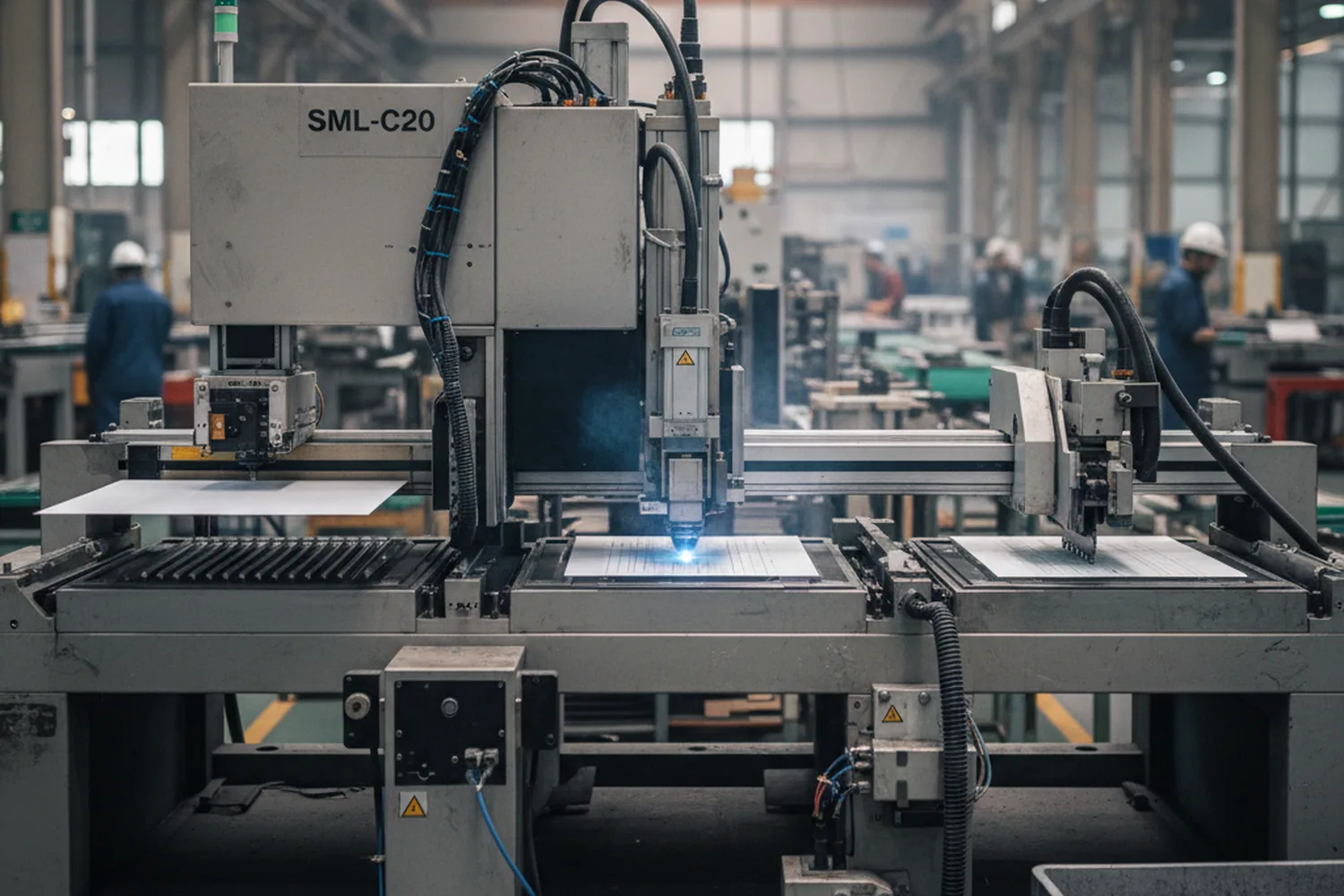
The machine runs three moves in a fixed order, and each one sets up the next. Load in a way that flexes the cell, or lay a scribe line the split can't follow, and the last move fails — which is why the three run as one sequence, not three knobs to turn on the floor.
Load on air
The Bernoulli cup lifts each whole cell onto the table with no contact grip, so it reaches the laser unmarked and unstressed.
Scribe at λ=1064 nm
The 30 W Q-switched laser scores a 40 μm line exactly where the cell will part — a narrow kerf that takes almost no silicon with it.
Split and place
The machine parts the cell along that scored line and sets the separated wafers down, so what leaves the station is already two, cut the same way every time.
Because the split follows the line the laser drew, the whole result rides on the scribe landing where it should. A cell mishandled or mis-scribed here becomes a broken or off-size wafer the next station can't use — found after the line has already handled it.
Load on air
Scribe
Split & place
The numbers
The Three Numbers the Cut Is Signed On
Three numbers say what the entry scriber holds, and they are the three your line is signed against. Read them and you know the class.
≥1600 pcs/h
Whole wafers, one cut on a 166 mm wafer
40 μm
Laser kerf, the width the cut removes
≤0.2%
Breakage rate
The kerf is the width the laser takes out of the silicon — narrow enough that the cut is micro-loss, removing almost none of the cell — and the ≤0.2% is what reaches the next station whole. Read the throughput against your own cell: it is counted as a single cut on a 166 mm wafer, so a different size or cut count moves the number.
Precision
How a 40 μm Line Lands in the Same Place Every Time
Precision here is a small target hit over and over: a 40 μm line — roughly half the width of a human hair — laid on the exact path the cell must part along, at ≤±0.1 mm, cell after cell.
- 1
The table finds the cell before the laser fires
Positioning holds ≤±0.1 mm, so the scribe starts from a known place rather than wherever the cell happened to land. Miss the path and the split follows the wrong line — an off-line split is an off-size wafer the next station can't place.
- 2
A consistent batch keeps the scribe depth matched
The machine is specified for cells whose thickness holds to ±10 μm within a batch, because a laser scribe is set to a depth: a batch that jumps in thickness runs too shallow on the thick cells and too deep on the thin ones.
- 3
One envelope covers every size it takes
The working format is 226×226 mm with a 300×300 mm module stroke, so the same precision covers every cell the machine handles, from 156 up to 220 mm.

Speed is not what separates the two scribers, either. The laser tracks the cut line at up to 500 mm/s — the same cutting-speed ceiling the high-speed machine runs at — so what sets the entry tier apart is throughput and configuration, not a slow cut. A compact single-station scriber simply runs one lane where a high-throughput line runs more.
The point of the tight numbers is not the numbers themselves; it is that a 40 μm cut only helps if it lands in the same place every time.
Cell scope
One Cell Type This Machine Won't Take
One boundary is worth stating before anything else: back-aluminum cells are outside this machine's scope. If your route runs a full-area aluminum back-surface cell, this is not the scriber for it — better known now than at commissioning.
What the machine takes
- Monocrystalline / PERC and similar cells — 156 to 220 mm, 120–220 μm.
- A 166–182 mm two-way split — standard tooling, ready out of the box for the common case.
What to settle before you order
- Any other split ratio — a custom tooling item, quoted separately; a tooling question, not a machine limit.
- Your cell type — confirmed against the list at left, so the machine matches the cell before the order rather than after.
If you're unsure whether your cell falls inside that scope, send its type and thickness and we'll confirm it against the machine before you commit to anything.
Downstream
What Sits Downstream
A scriber is only useful if the next station takes its wafers cleanly, so here's the single handoff that matters — the rest of the line lives on its own pages.
-
Stringing takes the separated wafers
The cut wafers feed a stringer, which solders them into strings; the docking detail sits on the stringer pages, not here.
-
The whole line is one click away
Which station runs which machine is mapped where it belongs, rather than repeated on this page.
Your floor
The Machine That Fits Almost Anywhere
Where most of the range asks your building for three-phase power and metres of clearance, this machine asks for almost nothing — a single-phase outlet, an air line, and a square metre of floor. Below is the SML-C20's own row; the full site conditions belong to the line utilities and layout page.
| Item | SML-C20 |
|---|---|
| Footprint | 1000×650×1500 mm |
| Weight | 400 kg (smallest in the range) |
| Power | 220 V / 50 Hz / 3 kVA · single-phase |
| Air | 0.5–0.8 MPa · φ12 mm inlet |
Other scriber
The High-Speed Scriber
If your line runs BC at volume, or you need a cut with no microcracks at all, the entry tier isn't where you should be — here's the other scriber, so you land on the right one instead of stretching this one to fit.

SML-C72 — High-Speed Laser Scriber
The BC and high-throughput machine: a lossless groove-and-cleave cut, the lowest chipping rate in the range, on a three-phase supply. Where you go when the line needs speed and a zero-microcrack cut.
Compare
Both scribers, side by side
Cut method, throughput class and where each fits — the two laser scribers on one page.
See the laser scribing machine pageAfter you buy
After You Buy
One line of the acceptance run turns on a size you sign, not a number the machine hits.
Your signed size decides the cleaving tooling
The SML-C20 ships with cleaving tooling standard for 166–182 mm two-way splits; accept a cell any other size and that run needs a fixture built to order. So the size on your drawing is what decides whether acceptance uses the standard tooling or a made-to-order one — settle it up front, and the machine is proven on the tooling your line will actually run.
See how acceptance is run
Get a proposal
Get Your Configuration Proposal
Tell us the cell and the split, and a proposal comes back — a small next step, before you commit to anything.
A configuration proposal back within 24 hours · email.