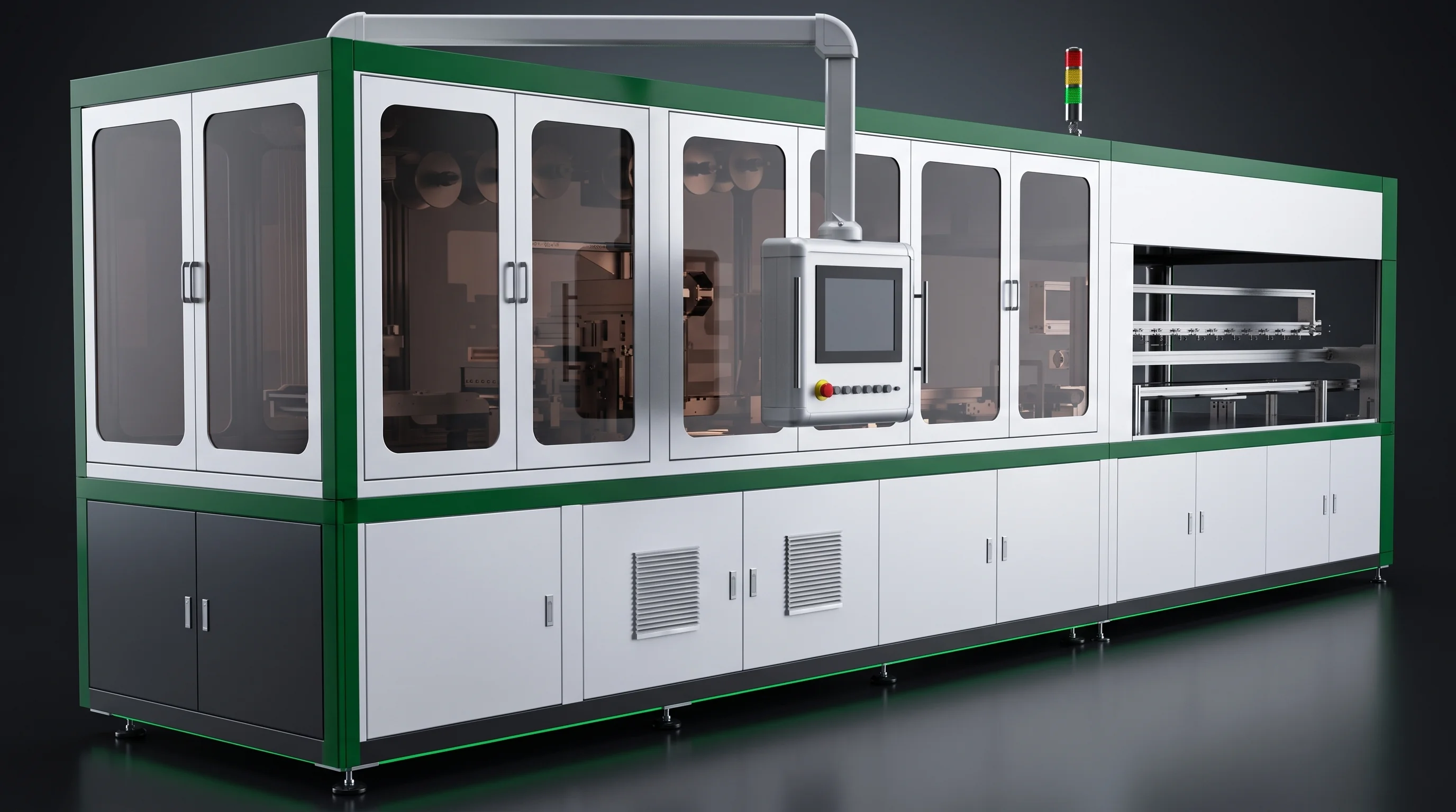
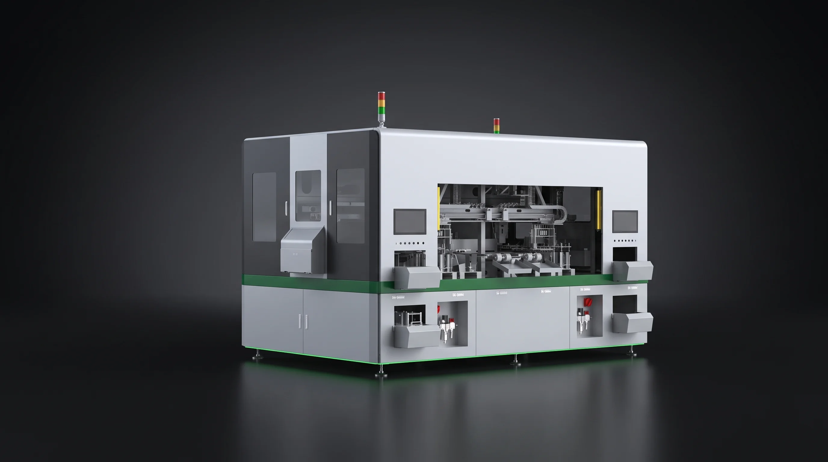
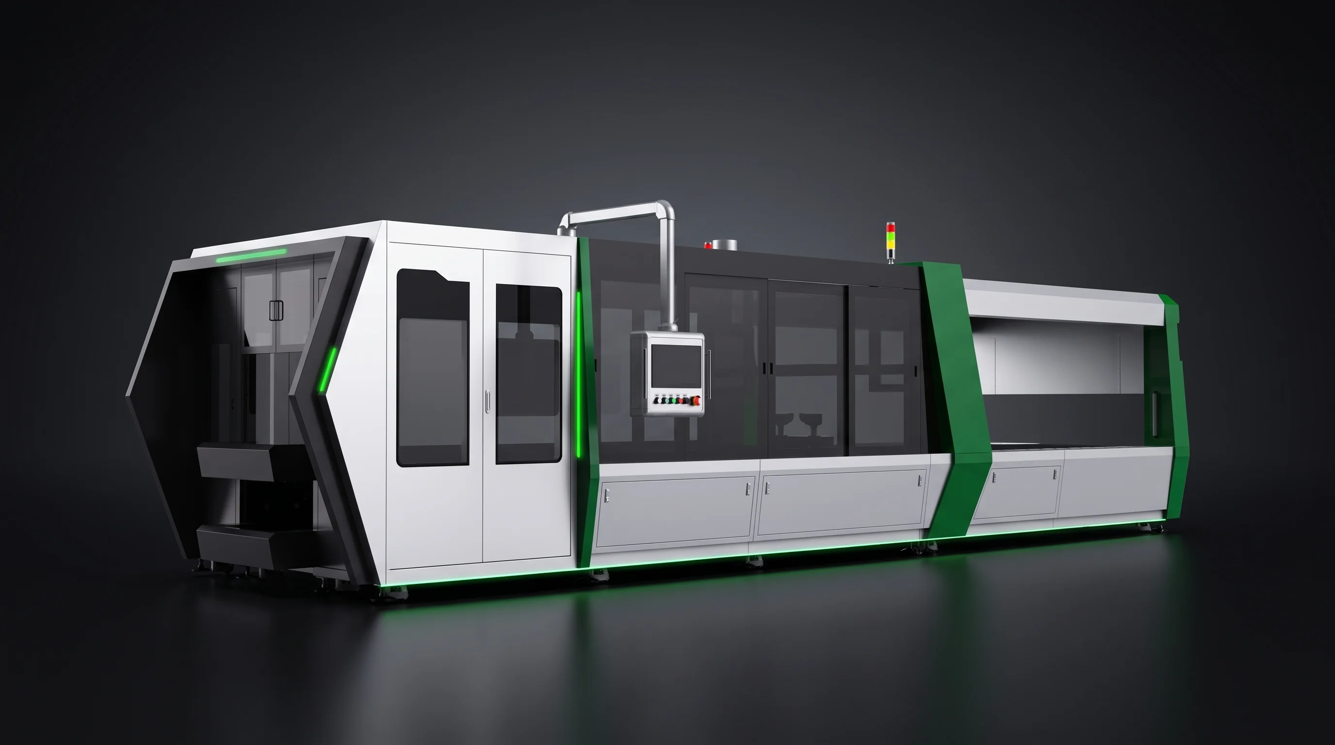
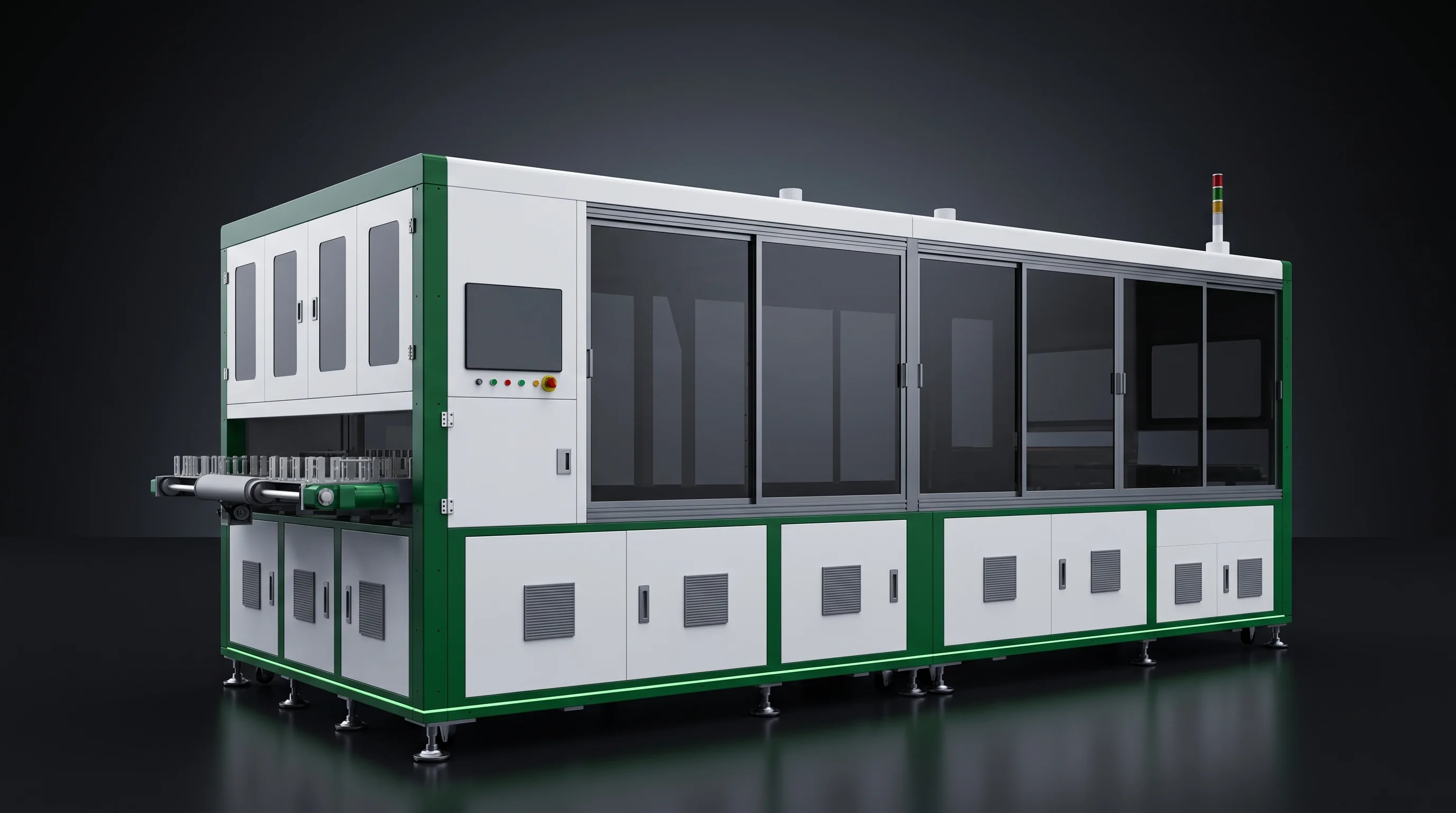
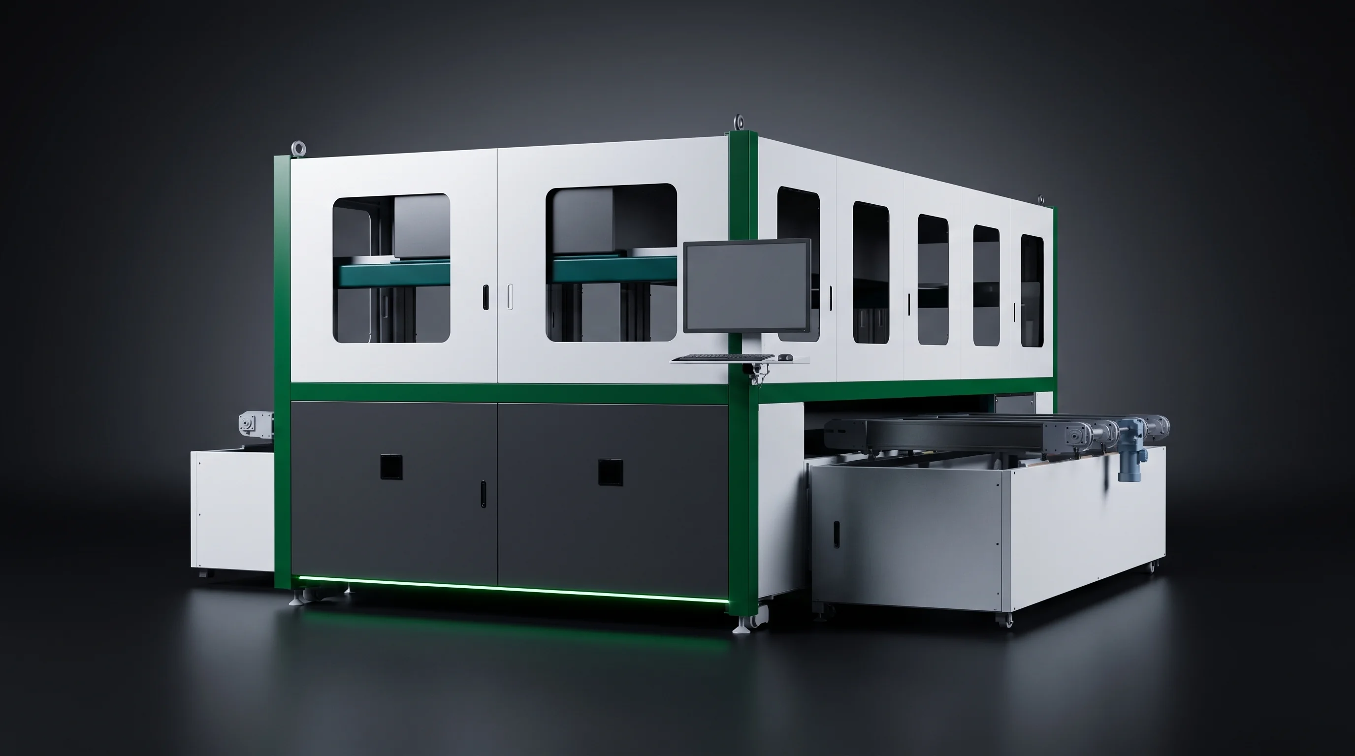
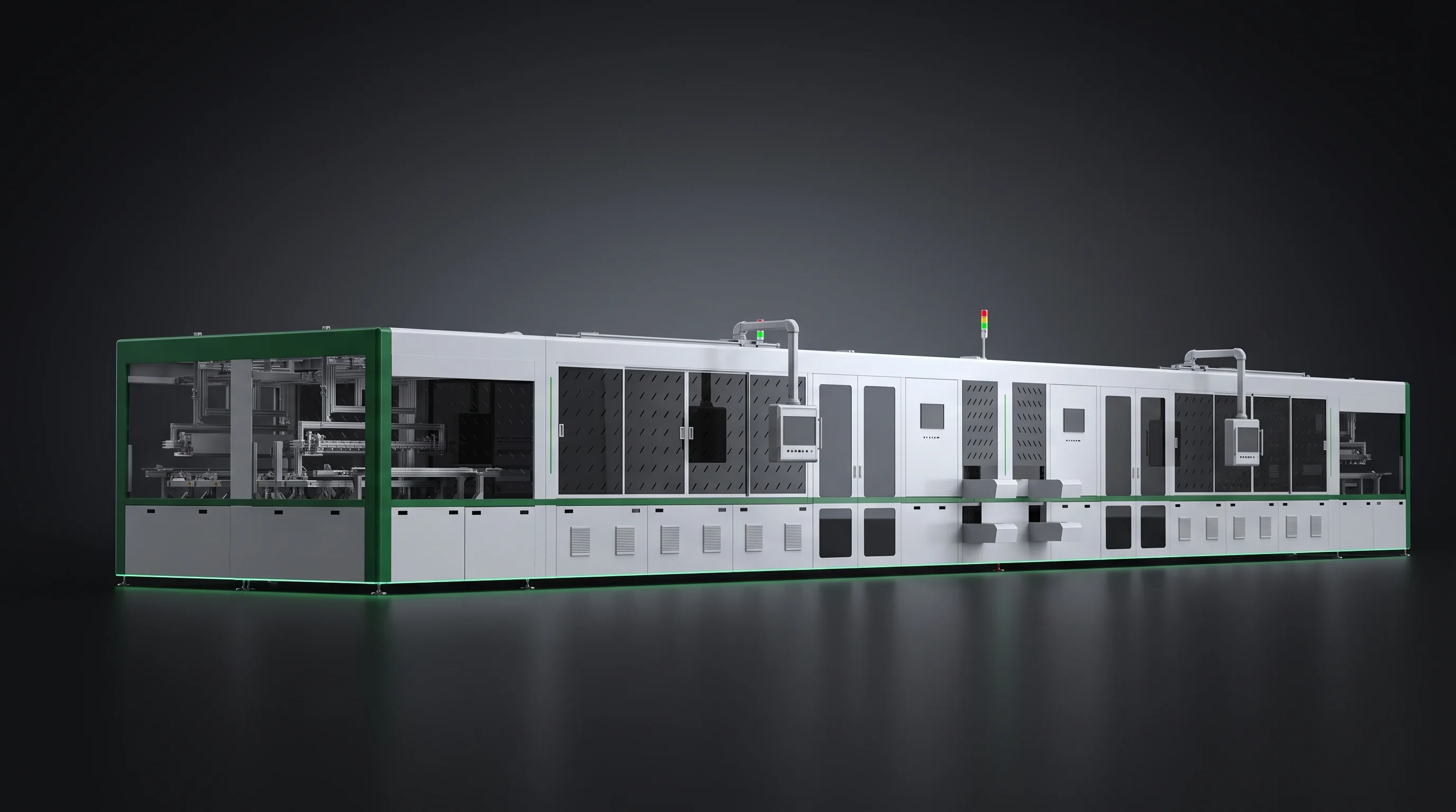
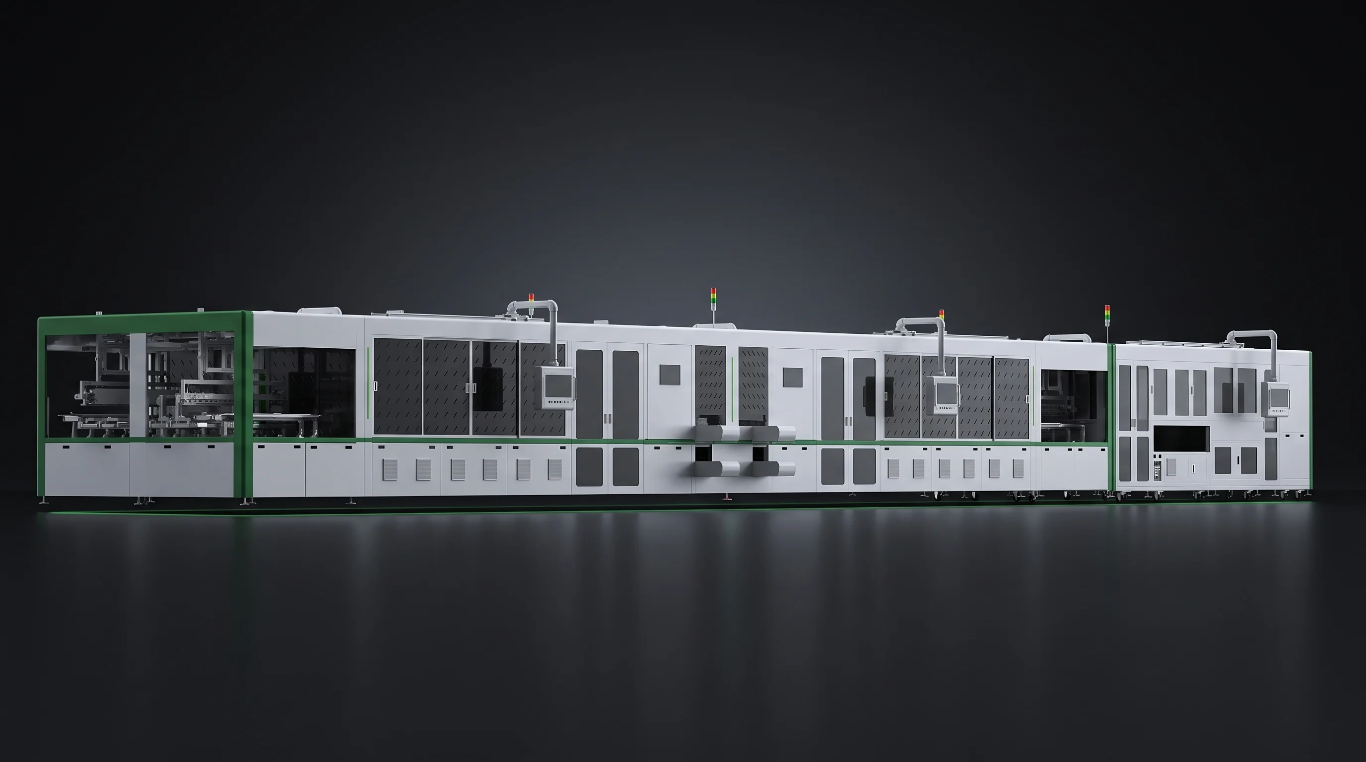
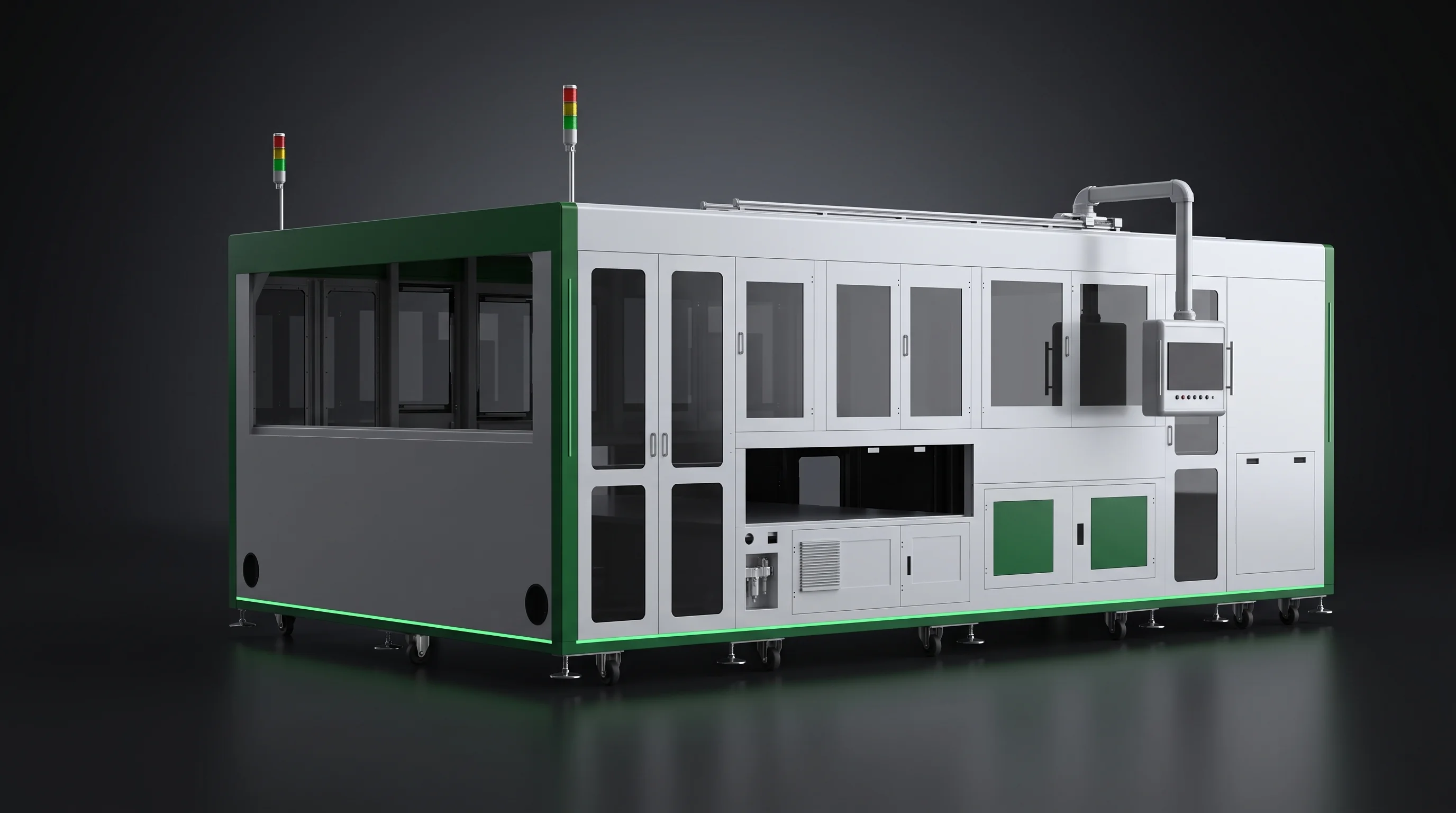
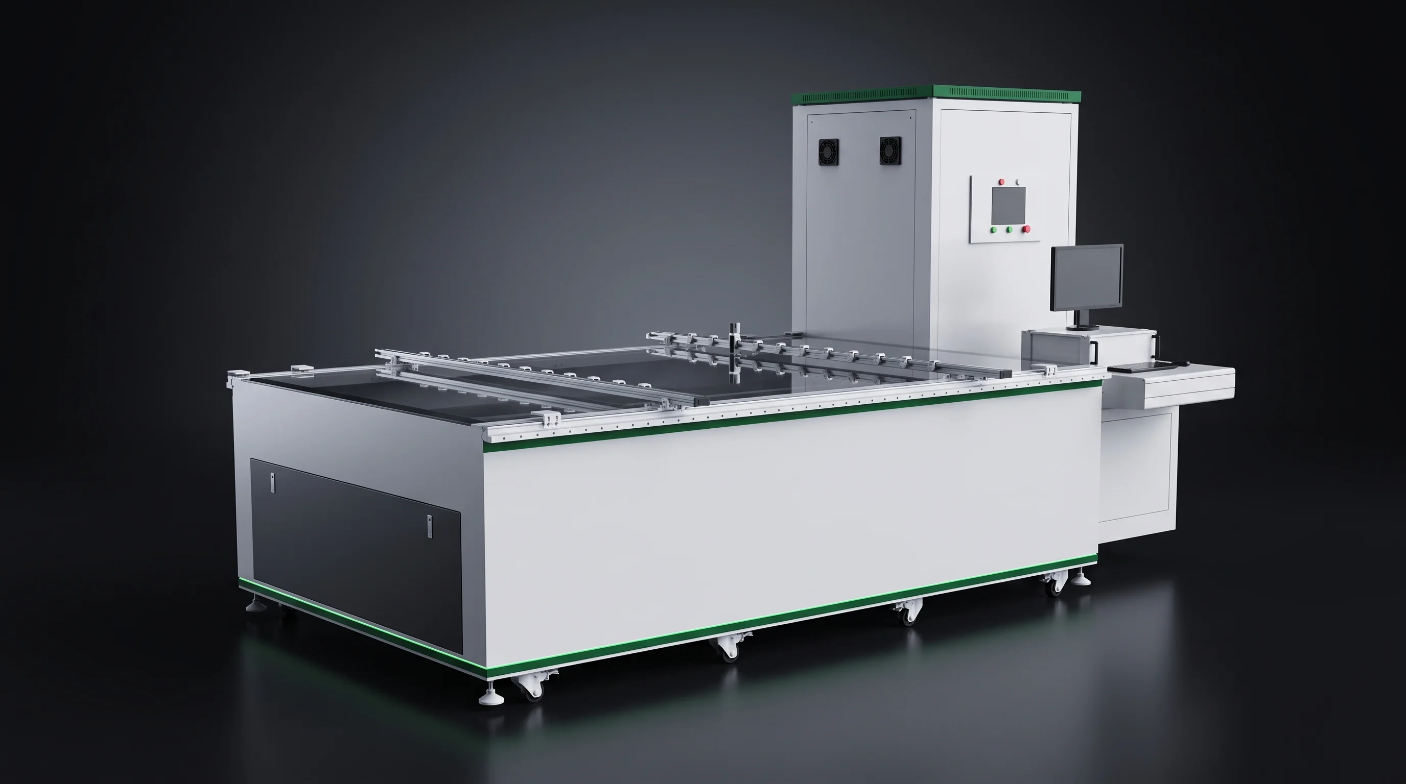
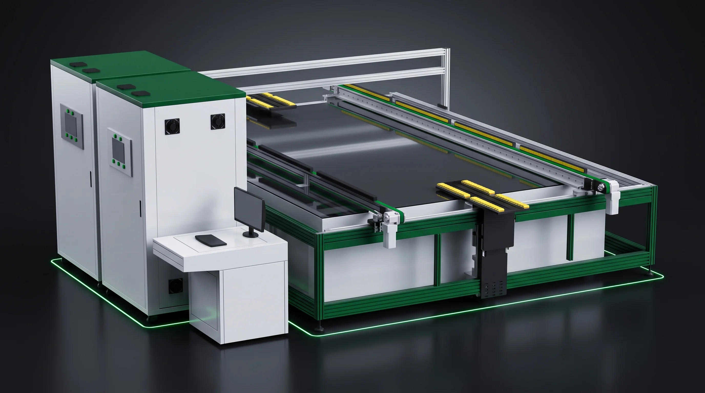
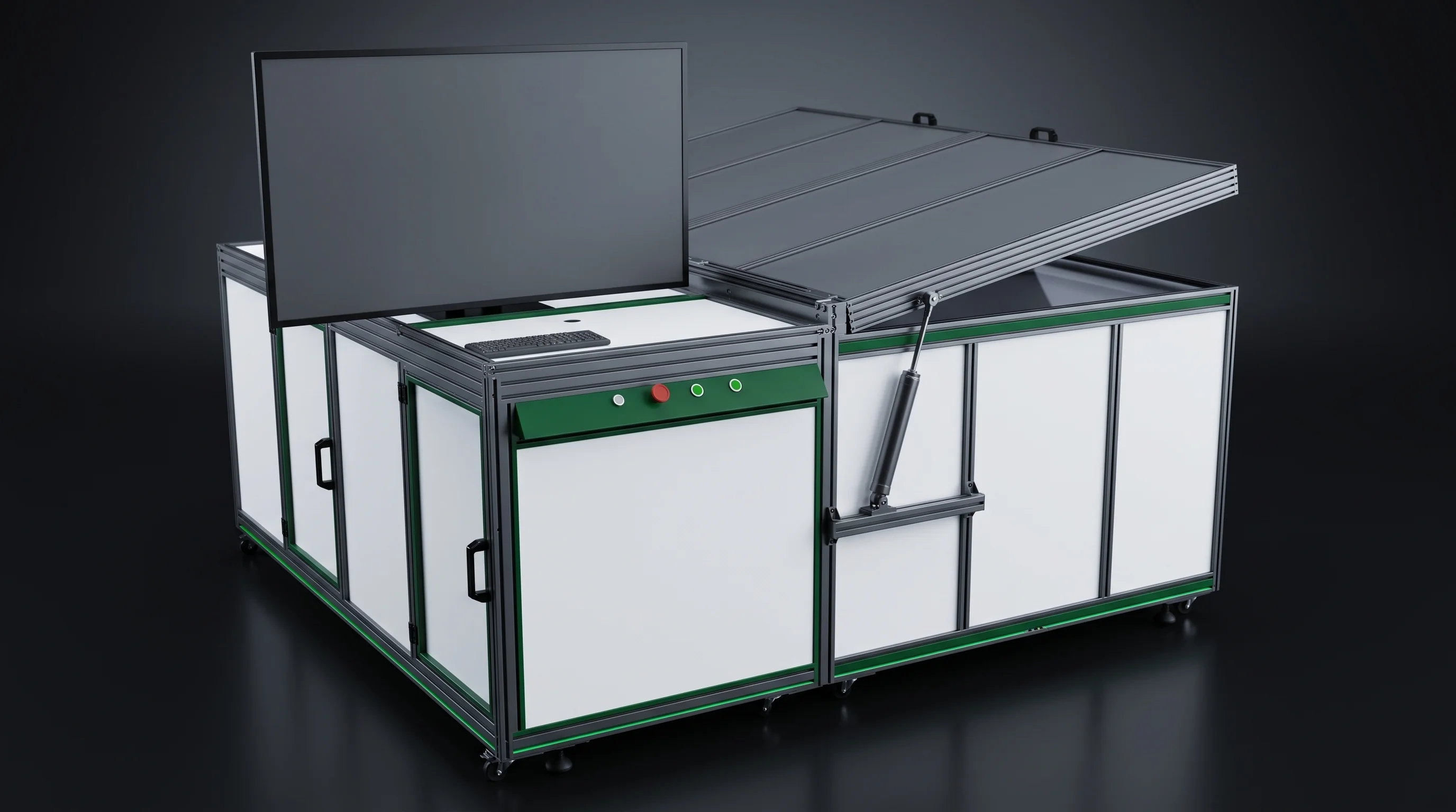
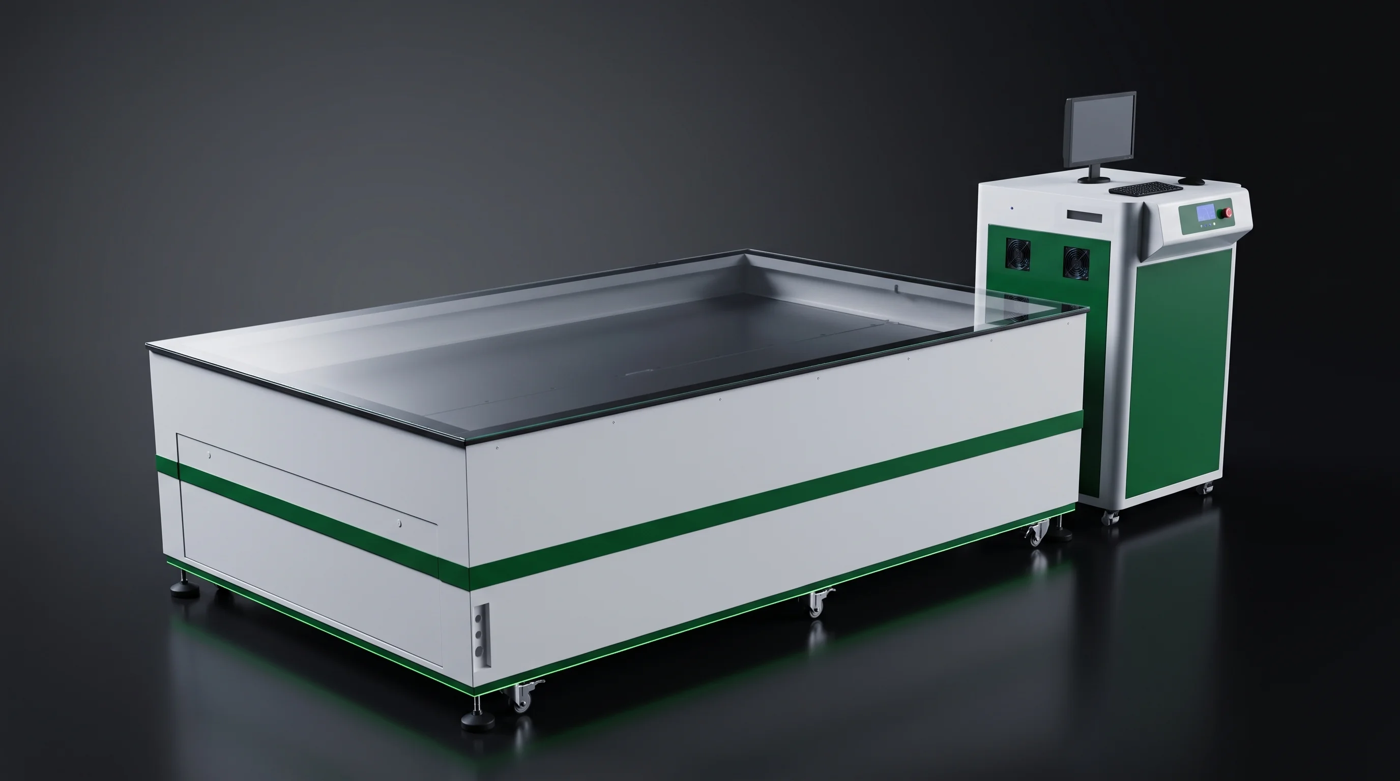
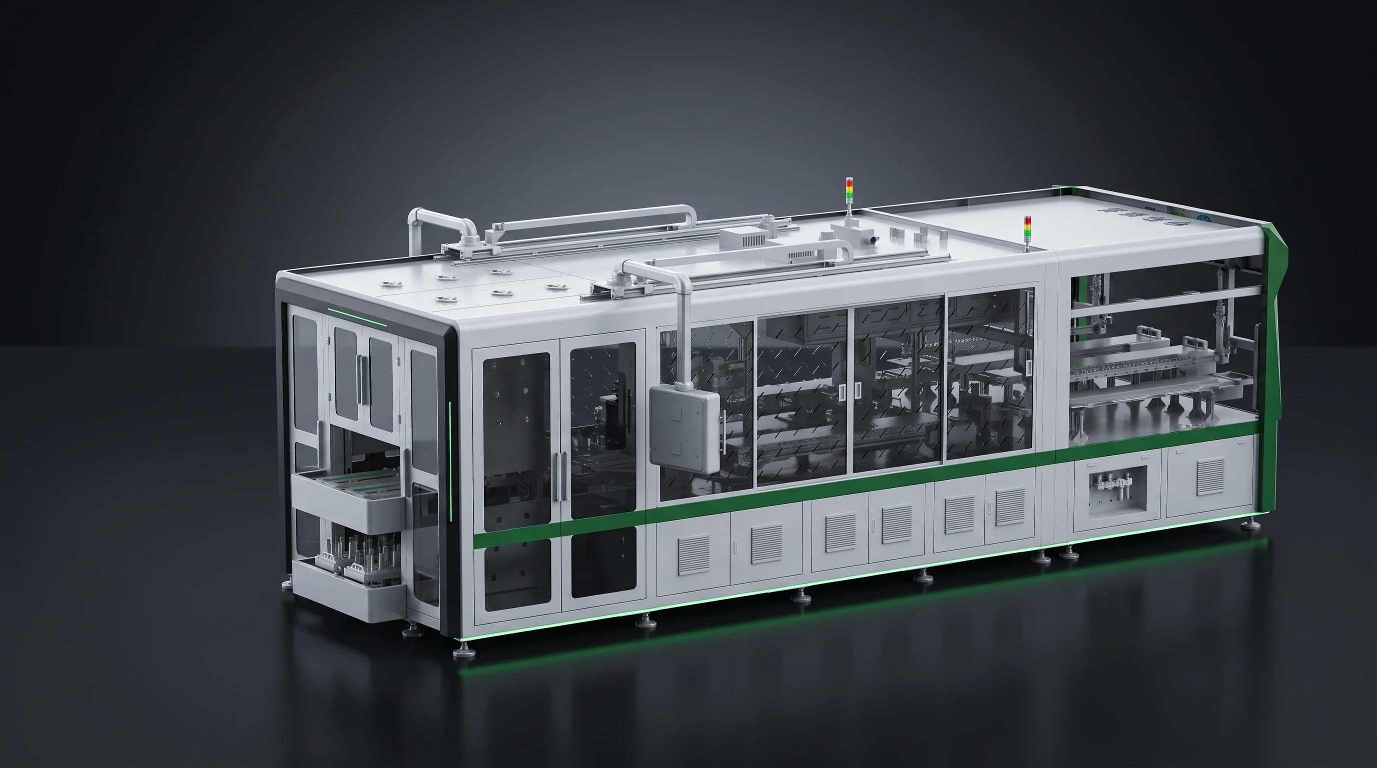
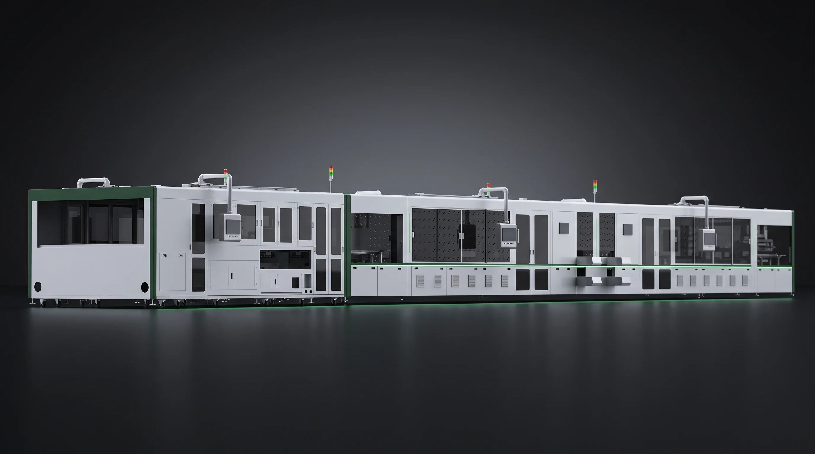
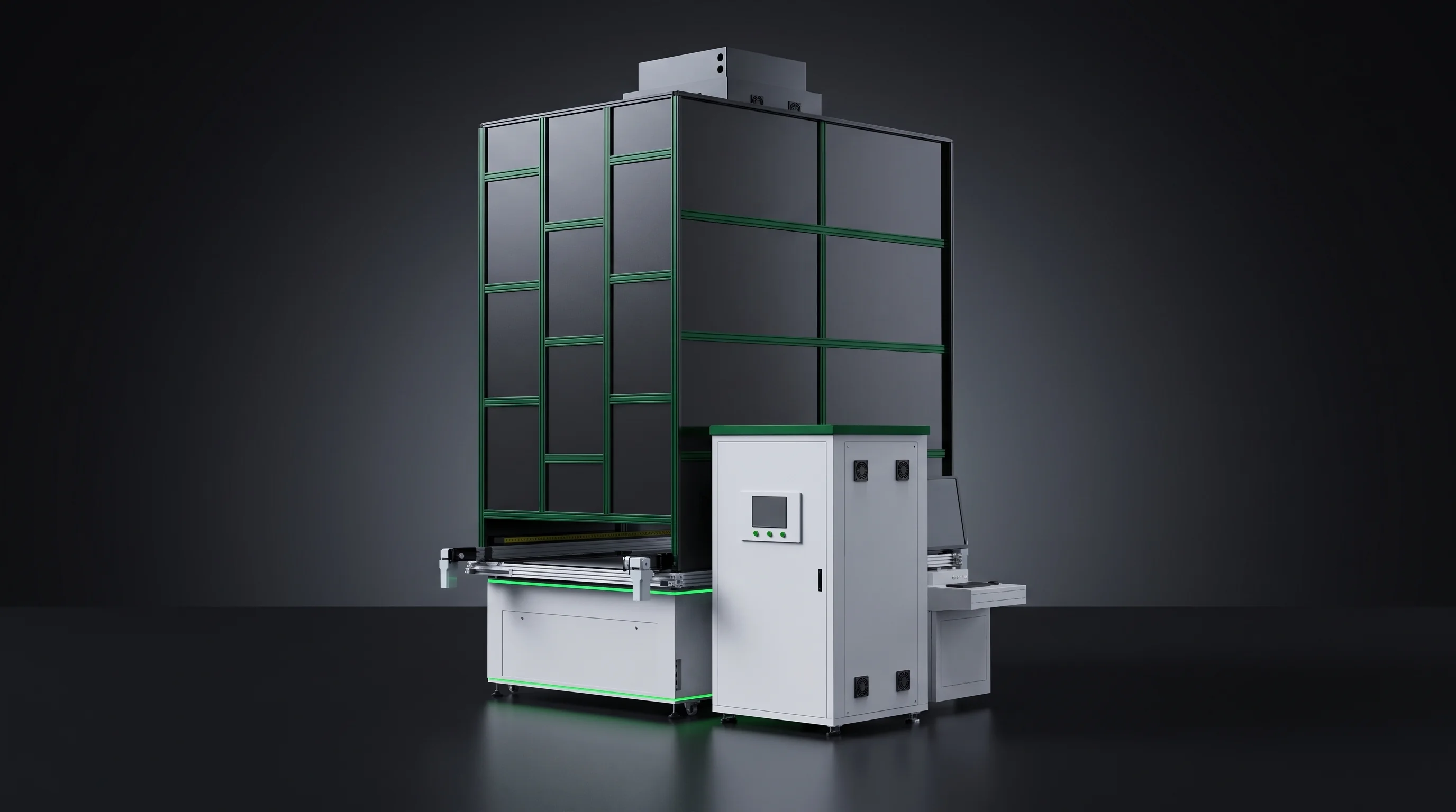
Solar Module Production Line Systems for Cell-to-Laminate Plants
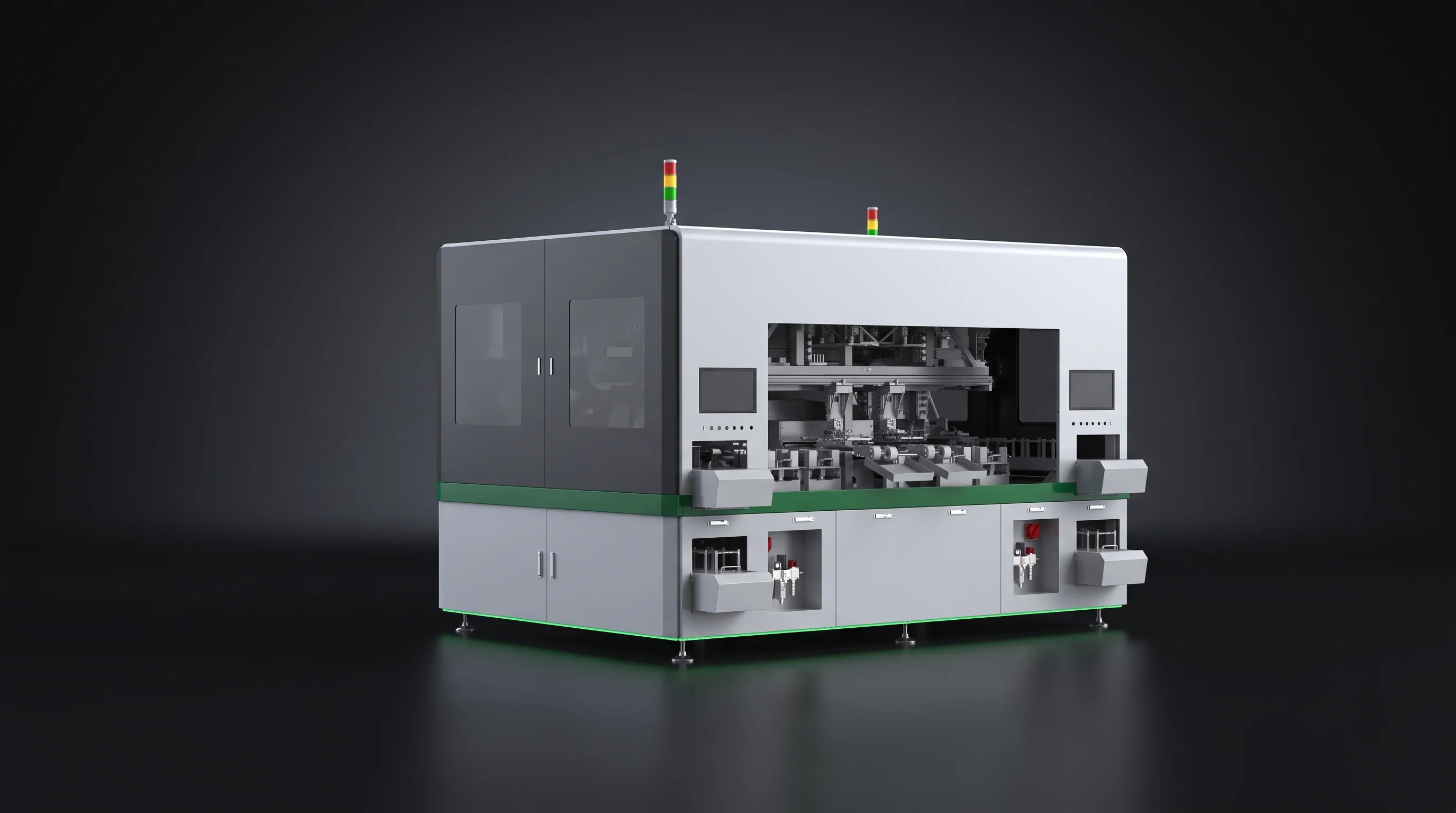
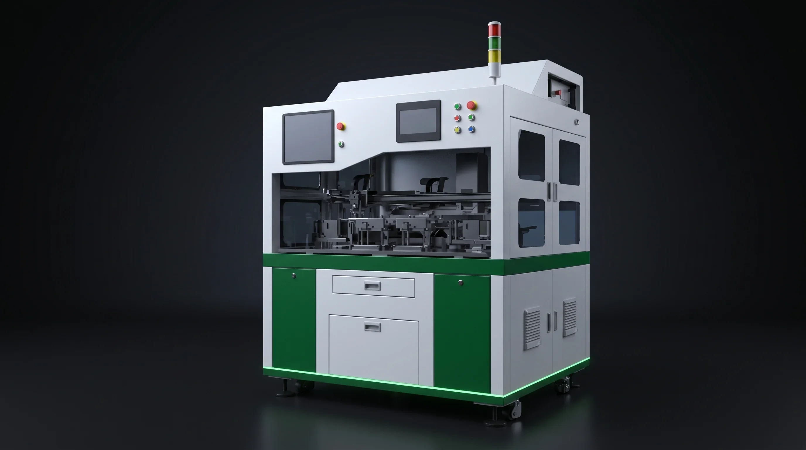
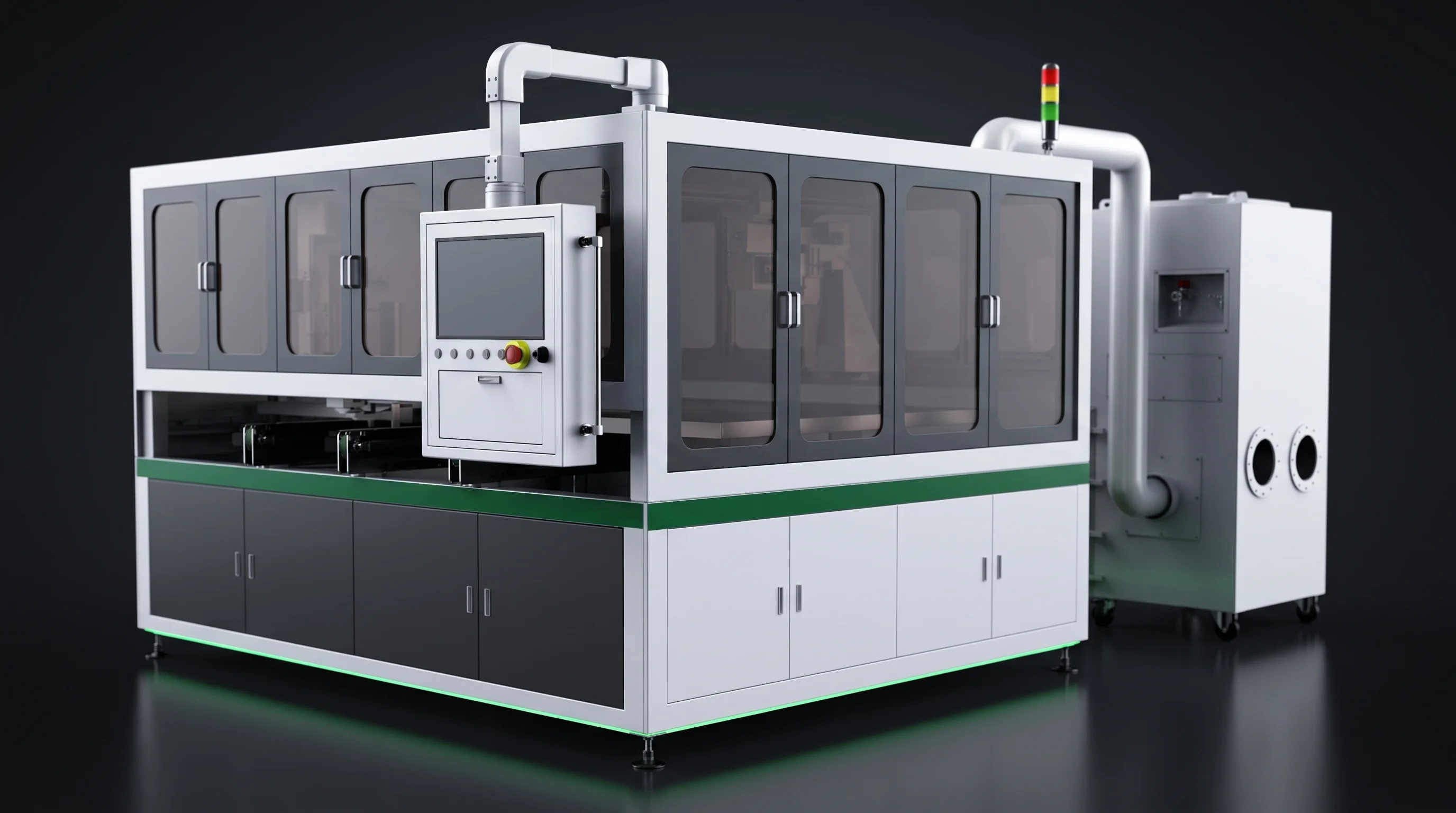
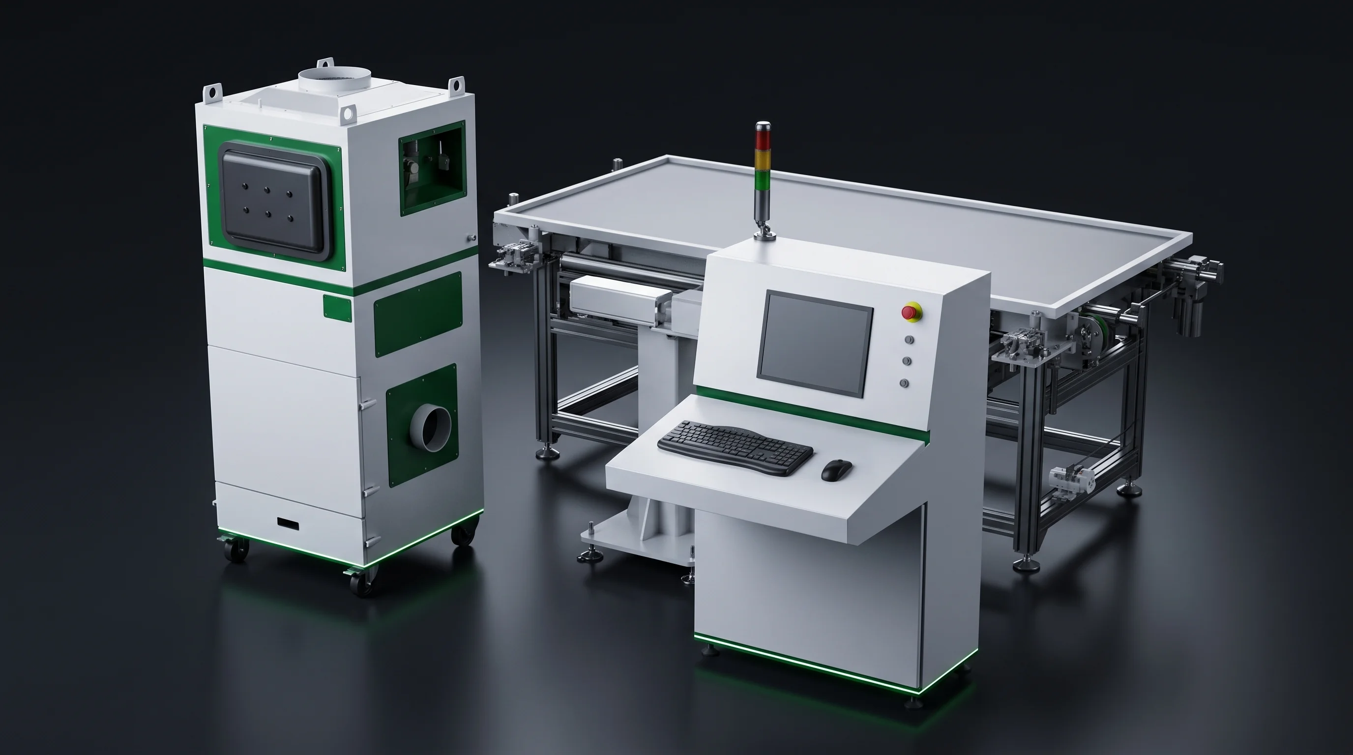
A solar module production line that starts where the tested cell arrives: laser scribing, tabber-stringing, robotic layup, bussing, EL and IV test and frame marking, with lamination left to the laminator already on your floor.
Six machine models carry full technical agreements. Each ships against one blueprint you define: your cell format, busbar count, string length and floor.
0.05 mmCell positioning on scriber and BC stringer
20 to 25Ribbon feeding sets, expandable to 25 busbars
ScribingStringingLayupBussingEL and IV testFrame marking
What the line covers
Solar Module Production Line Scope
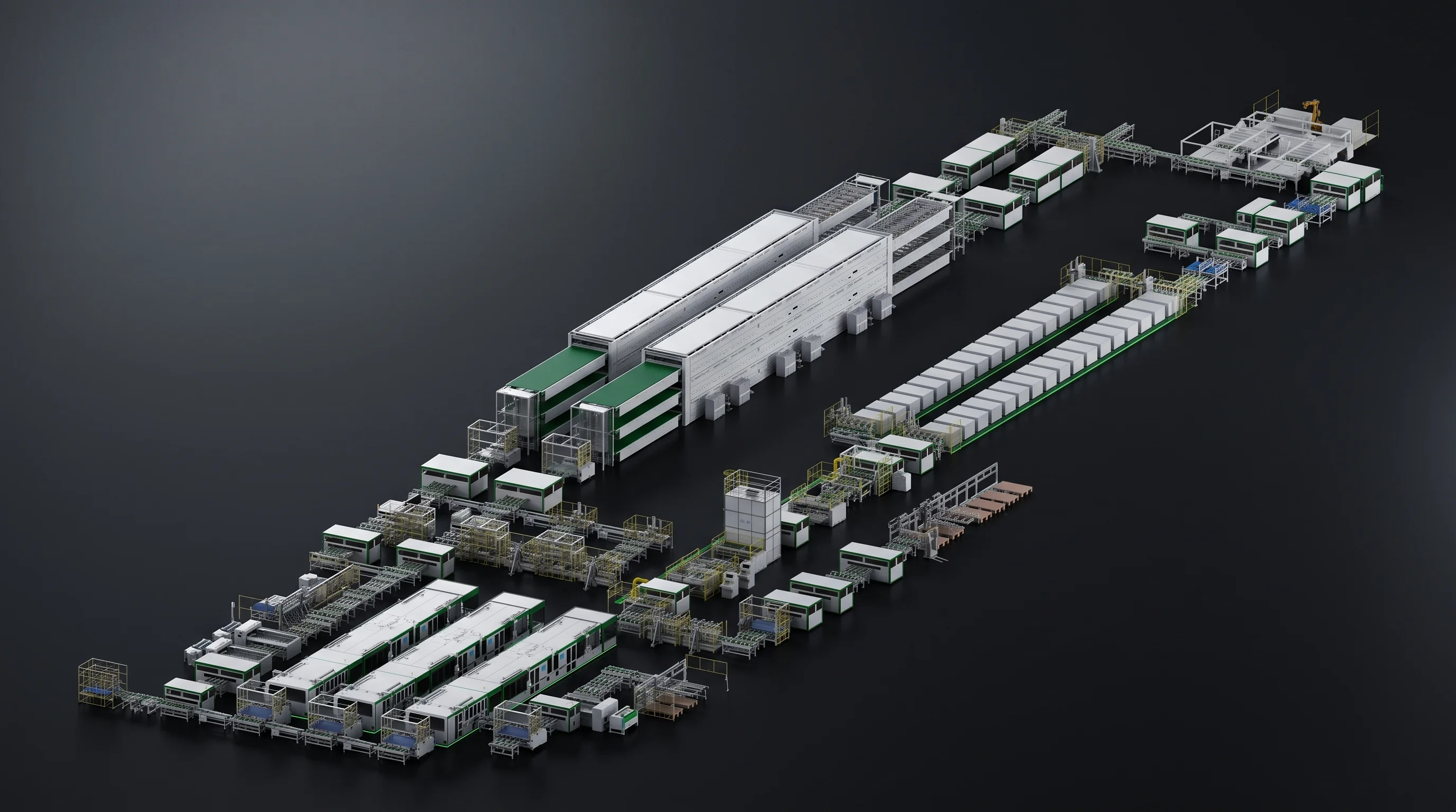
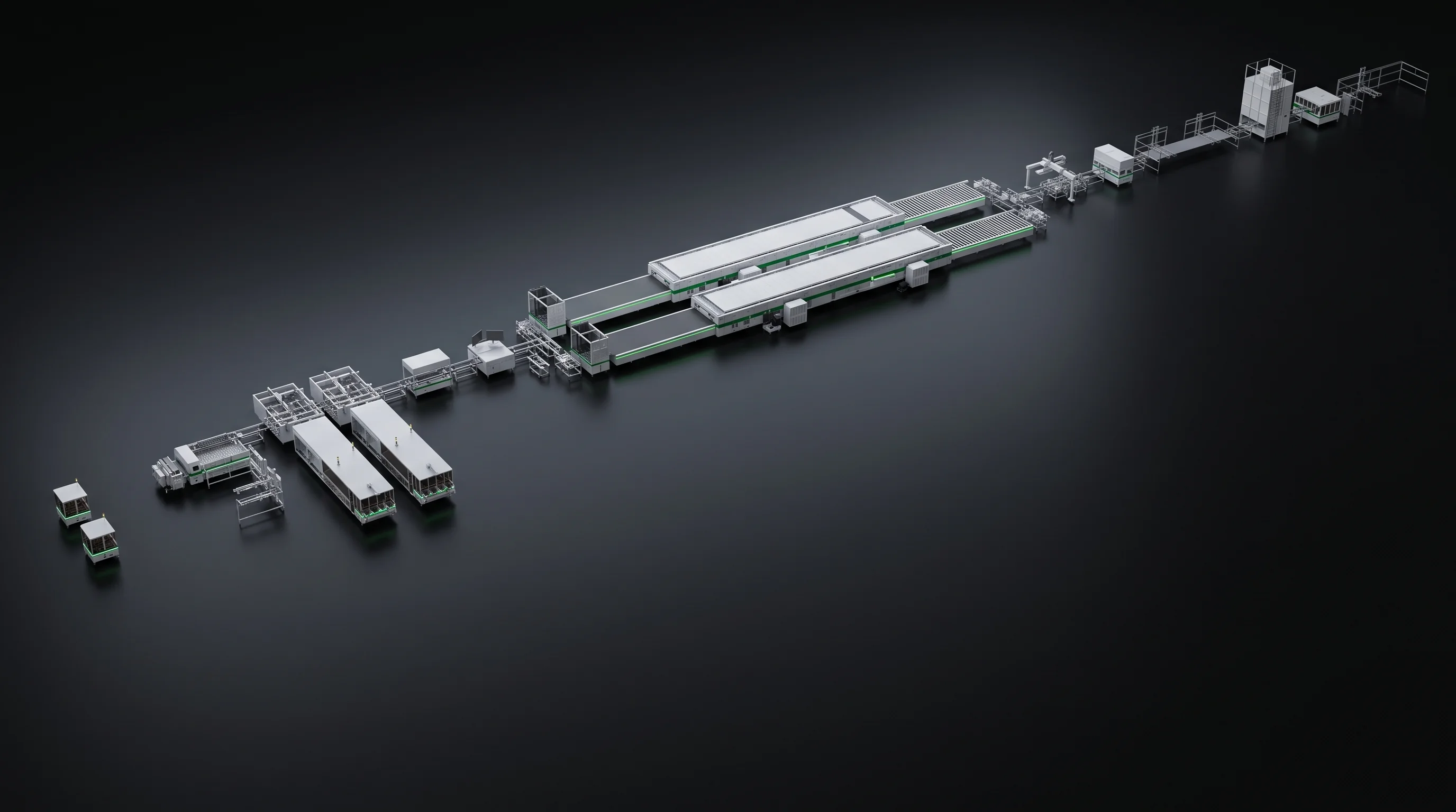
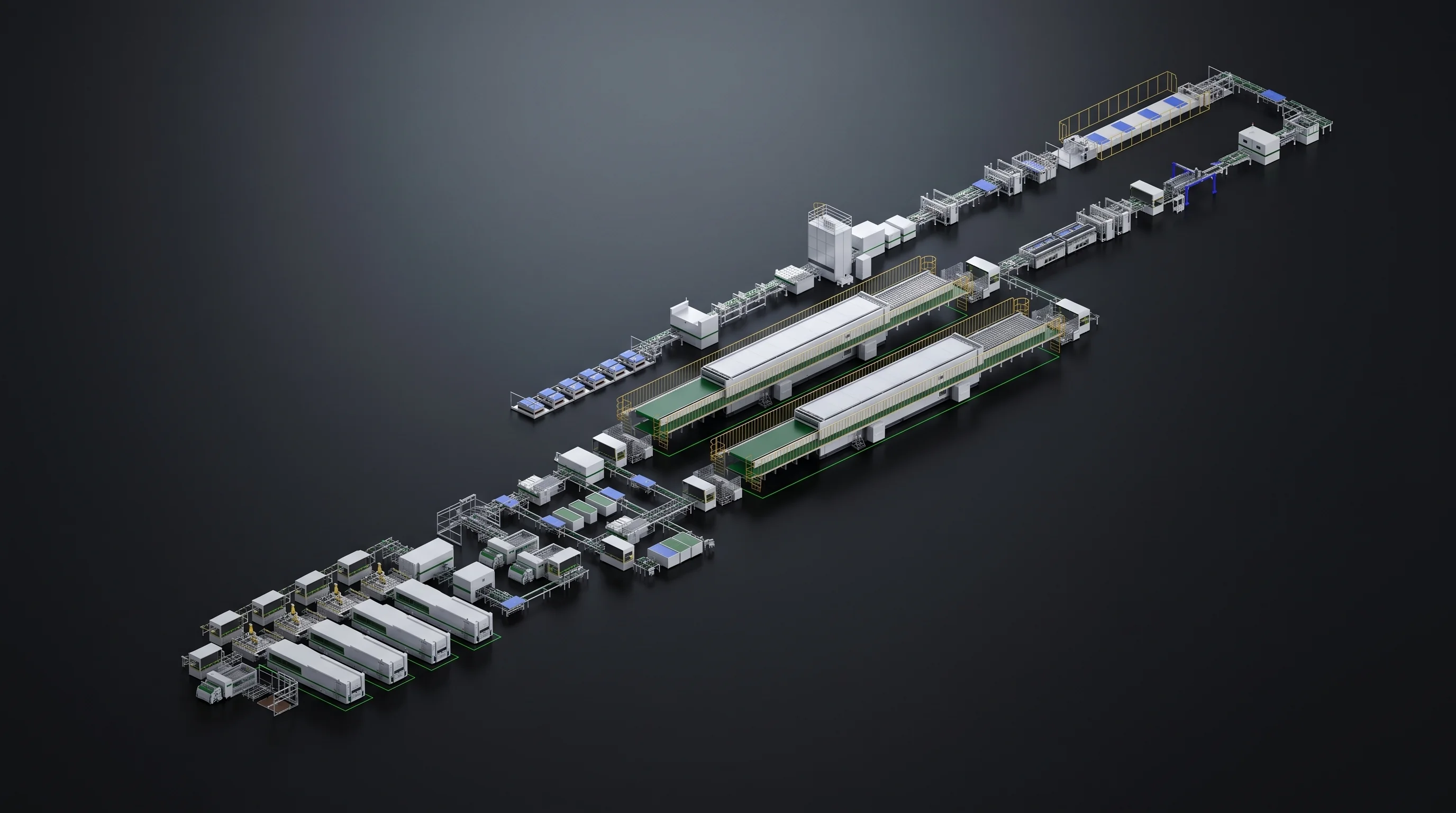
Three machine families plus the stations that close the loop between them. Together they form the 1 GW BC crystalline-silicon module line blueprint.
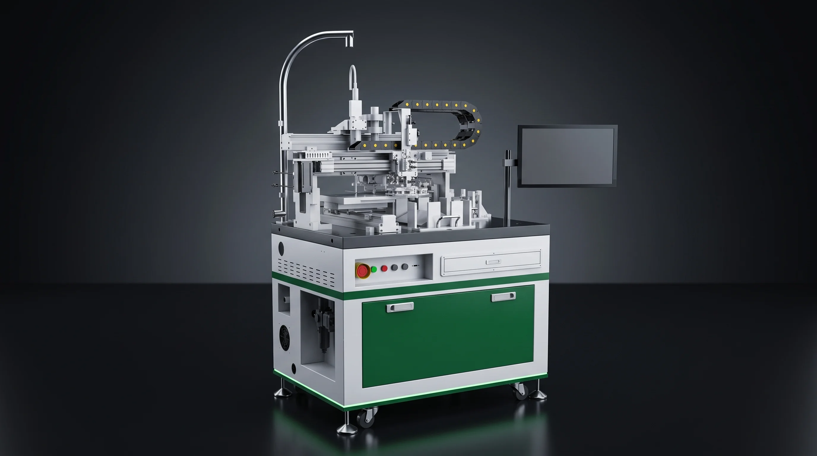
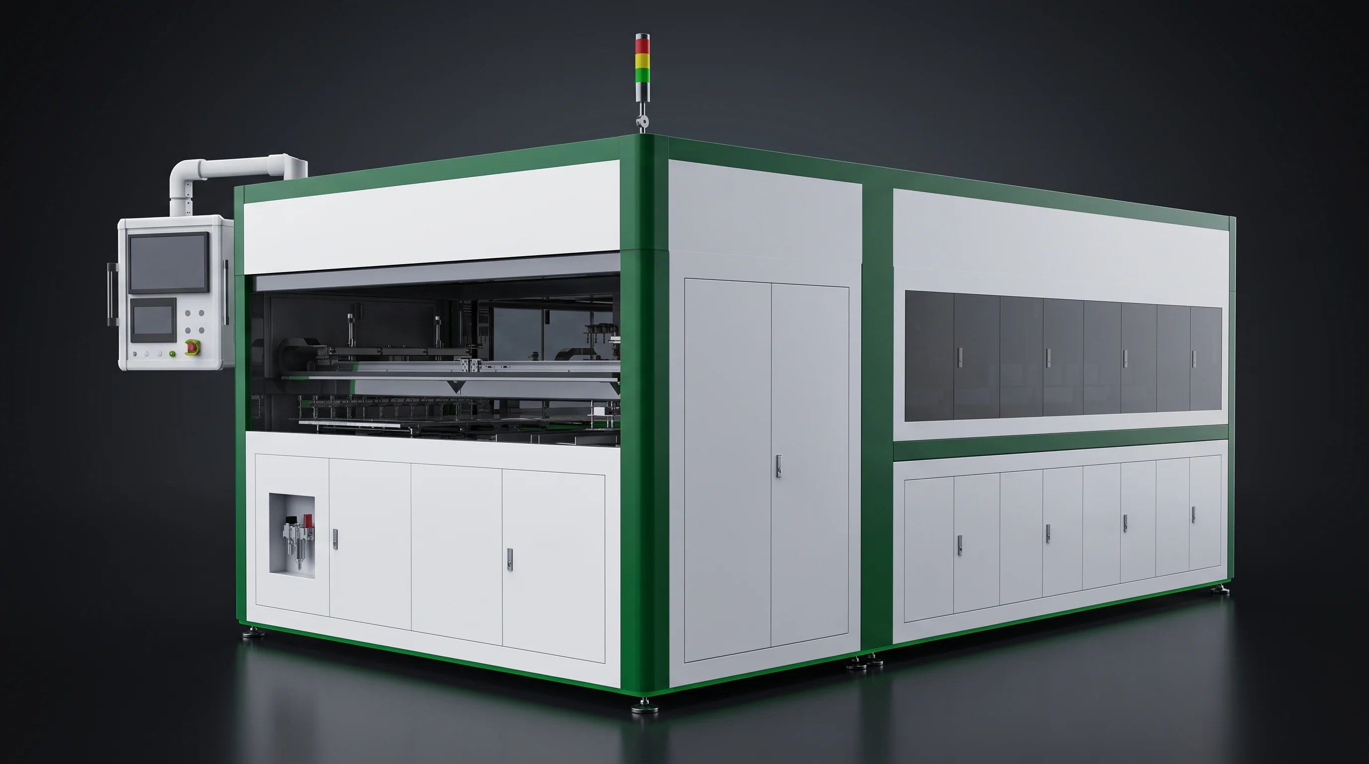
01Laser scribing. SML-C72 full-automatic grooving and thermal cleaving for BC, TOPCon and PERC; SML-C20 entry scriber with automatic cleaving and placing.
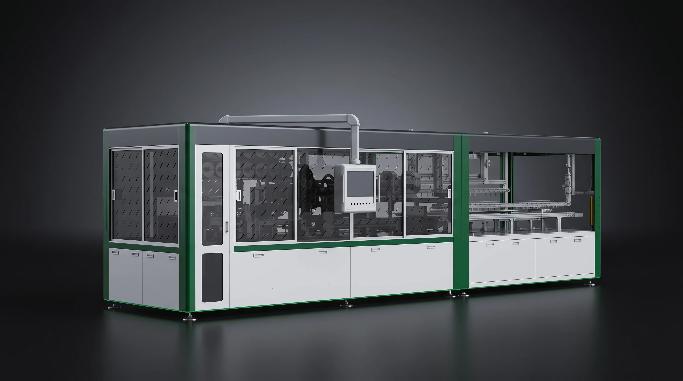
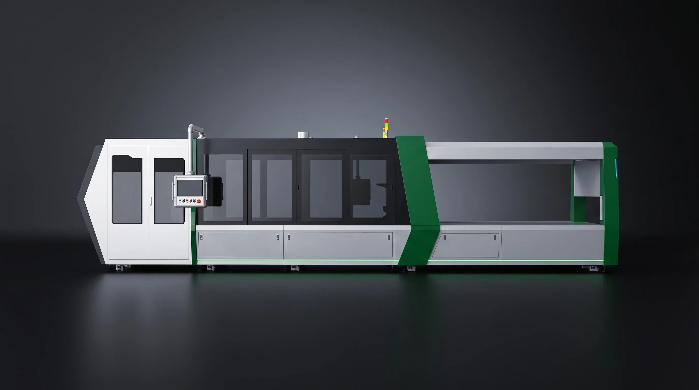
02Tabber-stringing. SML-S60 dedicated BC high-speed stringer; SML-S40 multi-busbar stringer; SML-S15 entry stringer for TOPCon and PERC.
03Robotic layup. SML-A6 CCD-guided station setting strings from the stringer onto glass.
04Downstream of layup. Bussing, EL and IV testing and frame marking machines that complete the module line.
Inside the span
Scribing, stringing, layup, bussing, EL and IV test, frame marking.
Outside the span
No ingot, wafer or cell equipment; no laminators, framing, cleaning or junction box stations.
1 GW BC line
Who buys what
Three Ways Plants Buy a Line
A full line, a BC upgrade inside a running TOPCon or PERC line, or one drop-in station. The documents you bring decide which reply comes back.
Every option is accepted against the same document: the parameter table of the technical agreement for the machines you order.
New plants: the full line
The project manager and equipment engineer bring a building drawing, a cell specification and an output target.
You bring
Building drawing, cell spec, annual output
You take
Station list, machine selection, layout fitted to clear height, floor load and utility entries
Existing plants: the BC upgrade
A BC order has landed and the installed stringer cannot make it. The floor stays; the stringer changes.
You bring
Current layout, new cell drawing
You take
Dedicated BC stringer, plus the matching scriber where the cell format changes
Running plants: one station
One station is the bottleneck or has aged out. The replacement drops into the existing conveying sequence.
You bring
Docking heights, string length
You take
A machine built to the string length and docking heights the line already runs
Six hand-offs
PV Module Production Line Stages
Each stage is defined by what it receives and what it passes on. Where a stage's output is not held to a figure, the next stage inherits the error.
Scribing
Positions, inspects, grooves and cleaves full cells; rejects leave at the machine.
Passes onHalf or one-third cells
Stringing
Positions each cell, lays flux-dipped ribbon, welds under infrared heat.
Passes onStrings held to length, pitch, straightness
Layup
Picks strings under CCD guidance and sets spacing on the glass.
Passes onPanel positioned within 0.5 mm
Bussing
Joins string ends into the module circuit.
Passes onComplete electrical layout
EL and IV test
Measures the laid-up panel before and after lamination.
Passes onPanel plus a measurement result
Frame marking
Applies, after lamination, the identification tied to the batch.
Passes onTraceable finished module
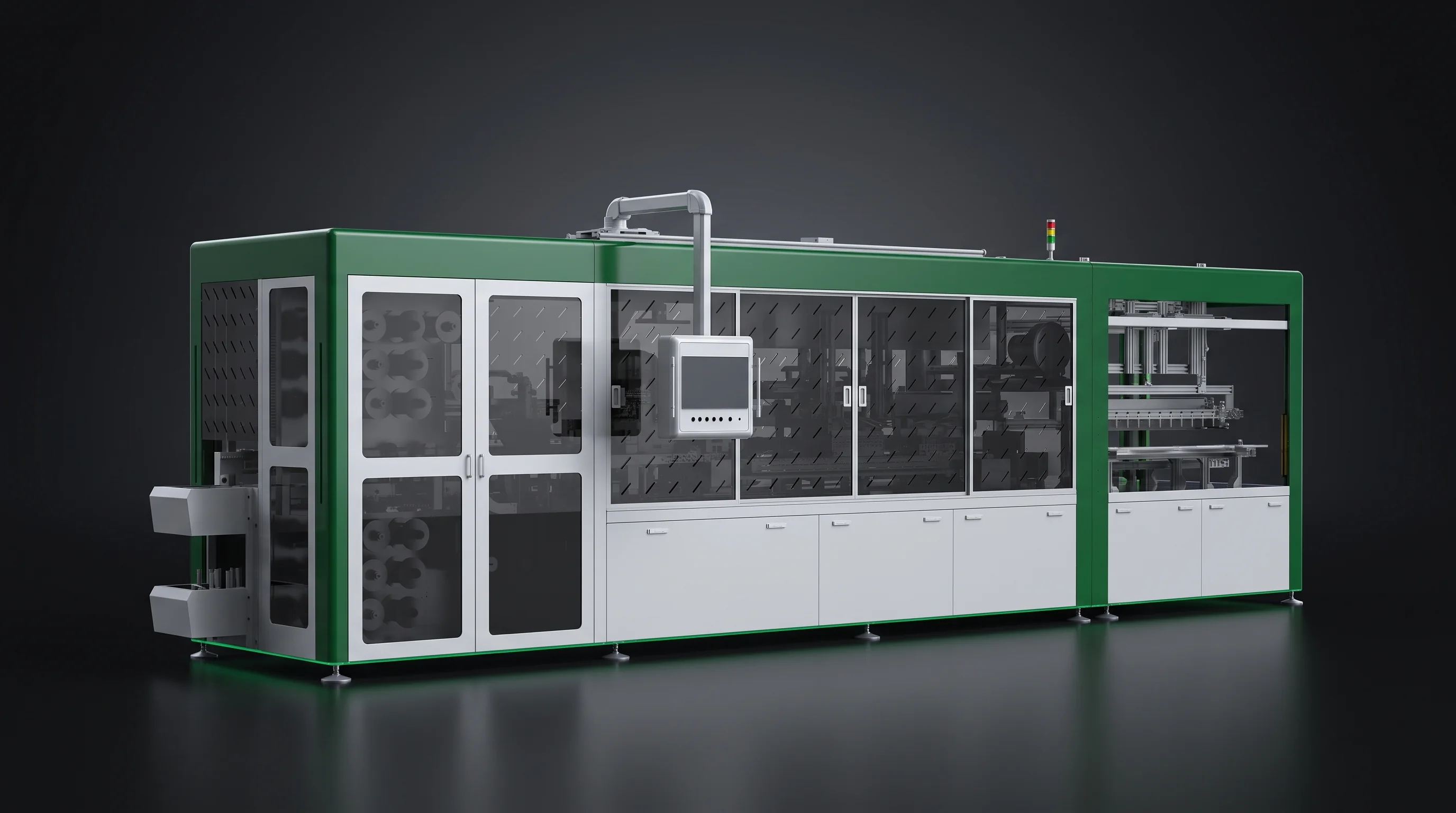
SML-C72Laser grooving and thermal cleaving. Water spray holds the scribing zone, the cleave is cooled with deionised water, and a heated section dries the cell before the stringer.
Stage one
Lossless Laser Scribing on the SML-C72
No mechanical breaking. A 60 W laser opens the groove and a 300 to 500 W laser drives the cleave, at up to 500 mm/s, with positioning within 0.05 mm and angular deviation within 0.04 degrees.
0.05%
Breakage at or below 0.05 percent on A-grade cells, written into the parameter table with uptime at or above 95 percent. A thermal cut leaves no micro-cracks at the edge and almost no dust, so no fire precaution is designed around cutting.
Why the cut is thermal
Mechanical breaking scores and snaps; the snap is where micro-cracks start and where half cells lose the strength they need at layup. A groove opened by the 60 W source and a cleave driven by the 300 to 500 W source separate the cell along the groove with no bending force at all. The half cell that leaves the SML-C72 has the edge quality of the full cell that entered it, and it reaches the stringer dry, cooled with deionised water and passed through a heated drying section.
Throughput, BC full cells
4800 pcs/h
Throughput, TOPCon and PERC, dual line
6800 pcs/h
Cell size and thickness
166 to 210 mm, 120 to 220 μm
Standard tooling
Two-cut
Checked on loading
Position and edge chipping
Corner loss, cracking, 90 degree flip
Contamination and scratches, rejected at the station
Checked on unloading
Whether the cell actually separated
Edge and corner chipping after the cut
Whether the two halves match in size
20000 h
Both lasers on the SML-C72 carry a 20000 hour warranty.
The 60 W grooving source and the 300 to 500 W cleaving source alike.
Stage two
Tabber Stringers in Three Tiers
Three stringers cover three jobs. All three hold angular deviation within 0.04 degrees and uptime at or above 95 percent, defined as one minus unplanned downtime over 24 hours.
01
SML-S60, the BC machine
BC cells 166 to 210 mm as half or one-third cells, 3BB-20BB with 25BB expandable, 110 to 200 μm. The only one of the three with negative cell pitch.
Throughput
4800 pcs/h half cells
Positioning
0.05 mm
Robot repeatability
0.01 mm
02
SML-S40, multi-busbar
PERC and TOPCon half cells over the same size and thickness band. Round ribbon of 0.29 mm is flattened in-machine to 0.12 to 0.15 mm thick over 4.8 to 6 mm.
3BB-12BB, 182 to 210 mm
3400 pcs/h
13BB-20BB
3200 pcs/h
Pull, front / back
0.5 N / 1 N
03
SML-S15, the entry machine
TOPCon and PERC cells 166 to 210 mm at 120 to 200 μm. Twelve ribbon feeding motor sets expandable to 20 busbars; sponge flux dip fed from a 10 litre tank with a low-level alarm.
Throughput
1100 pcs/h half cells
Transfer module
0.02 mm
Conveyor
0.01 mm
Figure
SML-S60
SML-S40
SML-S15
Cell route
BC
TOPCon, PERC
TOPCon, PERC
Magazines
200 small cells
Five: one working, two waiting, two empty, 300 each
Sponge flux dip, 10 L tank
Combined positioning
0.05 mm
0.1 mm
0.1 mm
Cell pitch
Minus 1 to minus 0.5 mm, plus 1 to 5 mm
Plus 1 to 5 mm only
Plus 1 to 5 mm only
Breakage, A-grade
0.25% at 120 μm and above
0.25% at 110 μm and above
0.25% at 120 μm and above
Swipe the table sideways
Why a dedicated machine
BC Stringing With Negative Pitch
Back-contact cells carry both polarities on the rear face, so the string is built with cells overlapping at the edge instead of standing apart. A stringer that can only open a gap cannot build that string, whatever tooling it is given.
Negative pitch is what makes the SML-S60 a BC machine rather than a re-tooled one. It sets cell pitch from minus 1 mm to minus 0.5 mm as well as plus 1 to 5 mm, holding pitch accuracy within 0.3 mm. The SML-S40 and SML-S15 offer positive pitch only.
Pitch accuracy within 0.3 mm on all three stringers; only the SML-S60 goes below zero.
20 to 25Ribbon feeding motor sets installed, expandable to 25 busbars, each switched in or out at the host computer
12 kgSpool capacity at 180 mm outer diameter and 160 mm width, leaded or lead-free
7.5 °CWelding temperature window, limits set at the host computer, alarm on any excursion
SML-S60 · infrared welding
What the joint has to prove
Infrared welding, blue film face down, tooling pressing flux-dipped ribbon onto the pad. Every figure below is an acceptance line in the parameter table.
Pull strength, 0.6 mm flat ribbon
0.5 N or more, at most one point per busbar below
Ribbon offset against pad centreline
Within 0.3 mm
String length
540 to 1400 mm
String straightness
0.5 mm
String defect rate
3 percent or lower
String re-feed rate
15 percent or lower
Positioning, four-axis robot
Repeats to 0.01 mm
What fits
Cell and Busbar Compatibility Envelope
Across the range cell size runs 156 to 220 mm and busbar count 3BB-20BB with 25BB expandable. No single machine covers the whole envelope, and the machine you buy is accepted against its own figures, not the range.
SML-C72
166210 mm
SML-C20
156220 mm
SML-S60
166210 mm
SML-S40
166210 mm
SML-S15
166210 mm
156166182210220 mm
SML-C20 · 226 by 226 mm table
Where the SML-C20 window is widest
156 by 156 mm to 220 by 220 mm on a 226 by 226 mm table, at 120 to 220 μm with a 10 μm batch tolerance.
Runs mono and PERC; aluminium back-surface cells are outside the window.
Standard cleaving tooling covers 166 to 182 mm two-cut; anything else is tooled to order.
0.25%Breakage ceiling on A-grade cells, carried with a thickness condition
120 μmLower thickness limit on the SML-S60 and SML-S15
110 μmLower thickness limit on the SML-S40; below it breakage rises, and that is said before the order
24-hour reply
Send Your Cell Drawing
Five inputs are enough for a machine selection and a layout proposal to come back within 24 hours, from an application engineer rather than a sales script.
The SML-A6 is the robotic layup station, handling modules 1650 to 2500 mm long and 990 to 1450 mm wide at 6 seconds or better per string.
Positioning system
CCD
Layup accuracy / string positioning
0.5 mm / 0.5 mm
String spacing
Settable 1 to 10 mm
Uptime
95 percent, loading time minus downtime over loading time
Material flow
Short edge in, long edge out
6 kWSingle-phase three-wire
0.6 to 0.8 MPaAir, 12 mm fitting
400 L/minAir consumption or more
3 tWeight, with door or fence
SML-A6
Stages four to six
Bussing, Test and Marking Stations
The range continues with the machines below, shown by name and appearance. The parameter table for each follows with the technical agreement for the model you select.
Names and appearance only on this page. Parameters for these models arrive with the technical agreement, not before.
SML-B200
Fully automatic bussing machine
Joins string ends into the module circuit after layup.
SML-I150
Combined scribing and stringing
Scribing and stringing in one machine body.
SML-I150L
Scribing, stringing and layup
Three stages in one footprint.
SML-L150
Combined layup and welding
Layup and welding joined in one station.
SML-C80
High-speed lossless scriber
Lossless scriber variant alongside the SML-C20B.
SML-C800
High-speed laser scriber
High-speed scribing for silicon cells.
SML-M200
Inline frame marking
Marks the frame in the line after lamination.
SML-M150
External frame marking
Marks outside the line where the layout needs it.
SML-T500
Module IV tester, level two
Middle of the three power levels.
SML-T-BIPV
IV tester for BIPV modules
Test bay sized for building-integrated formats.
SML-E
EL tester
Electroluminescence imaging at module level.
SML-T450
Module IV tester, level one
First of three power levels, with the SML-T500 and SML-T1000.
Selected by stage. Bussing after layup, EL and IV test at line-off, frame marking after lamination.
Quoted with a parameter table. Throughput, accuracy and footprint arrive as acceptance lines, not brochure claims.
Docked to your heights. Each station is built to the upstream and downstream docking heights you send.
Also in the rangeSML-S72 high-speed stringer, SML-S25 BC stringer, SML-S15B and SML-S60B BC stringer variants, SML-C20B lossless scriber variant, SML-T1000 IV tester. Each is quoted with its own parameter table once selected.
Detection at the stringer
Chipped corners
Edge chipping
Cracking
Print skew or offset
Catch it at the string
Inline String Inspection Options
Cell-level defect detection is built into the stringer. The acceptance threshold for each defect is defined at the host computer, so the judgement matches the cell grade you actually buy.
Two string-level inspections, optional on the SML-S60
String appearance inspection reads the finished string for offset, gaps and surface marks before layup.
String EL inspection reads virtual solder joints and micro-cracks in the finished string. Not standard equipment; specified on the order.
Found at module EL
One string and its neighbours
A virtual solder joint found after layup means opening a laid-up panel and pulling a string back out.
Found at the stringer
One string, taken out in place
The same joint costs one string, removed before the ribbon reaches the next cell.
Build basis
Changeover Tooling and Blueprint Basis
Every machine is manufactured and accepted against one blueprint specification you supply. Inside the compatibility envelope other products can be run, but changing busbar count or cell size needs the matching tooling, quoted separately.
Signed cell drawingSupplied with the technical agreement; the drawing every acceptance figure refers to.
5 to 10 working days after contractProduction cell and string type information the build is set against, plus the tooling list for further formats.
Tooling on the same orderDeciding at order stage which formats you will run puts that tooling on the same order, so the line never stops waiting for parts nobody ordered.
Needs new tooling
Busbar count change
Cell size change
Cleaving tooling outside 166 to 182 mm on the SML-C20
Carried without tooling
Ribbon feeding sets switched in or out at the host computer, 20 to 25 busbars on the SML-S60
Cell pitch and string length inside the set range
Defect thresholds at the host computer
What the building must deliver
Power, Air, Exhaust and Floor
Three-phase 380 V at 50 Hz on a five-wire supply across most of the range. The SML-C20 runs on 220 V single phase at 3 kVA and the SML-A6 on single-phase three-wire.
15 μmSolid particles, max
+3 °CPressure dew point, min
5 mg/m³Oil mist, max
Floor load 600 kg/m² or more on a level, vibration-free floor. Ambient 5 to 40 °C at 5 to 70 percent humidity without condensation. Exhaust drawn from the top of the machine in PVC duct.
Machine
Power, avg / peak
Air 0.6 to 0.8 MPa
Exhaust
Installation space, mm
Weight
SML-S60
30 kW / 45 kW per side
1200 L/min, two 16 mm hoses
600 m³/h
9000 x 3500 x 2800
7000 kg
SML-S40
40 kW / 60 kW
1200 L/min, two 16 mm hoses
600 m³/h
8000 x 1800 x 2650
4500 kg
SML-S15
15 kW / 20 kW
600 L/min, one hose
300 m³/h
7000 x 2000 x 2500
3000 kg
SML-C72
15 kW per side, 40 A
Per technical agreement
Per technical agreement
4000 x 2700 x 2700 body
5000 kg
SML-C20
3 kVA, 220 V
0.5 to 0.8 MPa, 12 mm inlet
Per technical agreement
1000 x 650 x 1500 body
400 kg
Swipe the table sideways
The SML-S60 and SML-S40 need their 1200 L/min through two 16 mm hoses at the same time, not one. That detail decides the air drop before the machine arrives.
Before ordering one station
Line Integration Interfaces
The SML-A6 docks to the stringer at 1230 mm and takes and returns glass at 950 mm plus or minus 50 mm. The SML-S60 string outlet couples directly to a layup machine or runs standalone; if it is to be coupled, the outlet is built to that machine's height and dimensions.
String length runs 540 to 1400 mm and string spacing into layup is settable from 1 to 10 mm. Send four numbers and the answer comes back as a yes or a no.
Upstream docking height
Downstream docking height
String length you run
Module dimensions
On your floor
Installation and Acceptance on Your Floor
Installation and commissioning are carried out by our own engineers. The procedure is the same wherever the plant is; overseas, travel and parts freight for installation, commissioning and later site visits are on the buyer's account.
Acceptance runs against the parameter tableThroughput, breakage, uptime, positioning, pull strength, ribbon offset and pitch accuracy, line by line. The document to read before signing, and the one that settles any later disagreement.
What you supply during the windowQualified raw material in sufficient quantity and technically competent operators, so the figures are measured on your cells with your people.
Closed by signature on that tableEvery figure on this page that belongs to a machine you order appears in it.
Before acceptance
Operator Training Before Acceptance
Training is free and takes place before acceptance, at least once and at most twice, scheduled so the operators who sign off acceptance are the ones trained on it. The split below is fixed in the technical agreement: principle first, then operation, then the process parameters that decide breakage and pull strength, then system parameters and maintenance.
10 hOn-site operation training
3 hCommissioning training
+1Safety session
Ten hours on site, hour by hour
Operating principle
1 h
Operation
4 h
Process parameters
4 h
System parameters and maintenance
1 h
Commissioning
3 h
After acceptance
Warranty and Response Commitment
Warranty is one year free of charge, followed by lifetime maintenance service. After a written notice reaches us, the clock below starts.
48 hResponse after written notice
72 hSolution delivered
Wear parts, supplied for the life of the machine
Suction cups, springs and filter elements sit outside warranty but are supplied for the life of the machine, priced as ordered.
Knowing which parts sit in that category at order stage lets you stock them rather than wait for them.
Outside warranty
Damage from misuse, from operation outside the specified conditions and from force majeure, and any claim after the warranty period, where lifetime maintenance service applies instead.
One blueprint
Each machine ships and is accepted against the single cell and string specification you sign.
Two comparisons
Choosing a Solar Module Production Line
Two comparisons decide most solar module production line selections: how the cell is cut, and whether the BC stringer was built for BC or re-tooled for it.
Scribing
Mechanical cleaving
Laser groove + thermal cleave
How it separates
Breaks the cell along a scored line
Separates without mechanical force
Cut edge
Edge damage and micro-cracks
No micro-cracks, minimal surface damage
When it shows
Often not until module EL
Read at the scriber, both ends
Breakage, SML-C72
—
0.05 percent or lower
The figure to compare across scribers is not headline throughput but breakage and the thickness at which it is guaranteed.
Stringer for BC
General stringer re-tooled
Dedicated BC stringer
Cell pitch
Positive only
Minus 1 to minus 0.5 mm, and positive
Busbar count change
Through tooling
Through tooling, 20 to 25 sets switched at the host
Pitch it was not built for
Cannot produce it
Built for it
The line to ask about
A parameter table listing positive pitch only
SML-S60
Where a supplier offers BC on a machine whose parameter table lists positive pitch only, that is the line to ask about.
Edge damage hidden until module EL.Half cells reach layup with their strength intact.
From enquiry to signature
Solar Module Production Line Project Steps
Five steps, each with a named owner and a document that closes it.
01
Enquiry
Cell drawing, busbar count, cell thickness, target string length, output target and, for a single station, the docking heights. Machine selection and layout proposal within 24 hours.
OwnerOur application engineer
02
Technical agreement
The parameter table for the machines selected: throughput, breakage, uptime, positioning, pull strength and every other acceptance figure. You review it against your own quality standard and sign the cell drawing.
OwnerYour process lead, our engineering
03
Blueprint confirmation
Within 5 to 10 working days of contract signature, the production cell and string type information the machines are built against, plus the tooling list for further formats.
OwnerYour production planning
04
Installation and commissioning
Our engineers install and commission on your floor against the utility, floor load and footprint requirements confirmed earlier.
OwnerOur field engineers
05
Training and acceptance
Training runs first, then acceptance against the parameter table with your material and your operators, closed by signature on that table.
OwnerYour operators, our engineers
Start a project
Start a Solar Module Production Line Project
Send email, phone, country and requirements, and a reply comes back within 24 hours. Drawings can follow by email; the first reply already names machines and a layout direction.